
Buckling restrained structural brace assembly

a structural brace and restraint technology, applied in the direction of girders, joists, trusses, etc., can solve the problems of reducing the seismic performance of the brace, so as to enhance the seismic performance and simple and economical

Inactive Publication Date: 2006-11-09
QI XIAOXUAN +1
View PDF0 Cites 25 Cited by
  • Summary
  • Abstract
  • Description
  • Claims
  • Application Information

AI Technical Summary

Benefits of technology

[0007] The present invention is directed to a buckling restrained structural brace assembly that provides for a simple and economical way to enhance the seismic performance of braces.

Problems solved by technology

Nevertheless, observations of recent major earthquakes indicate that under performed structural elements in buildings and other structures result in a significant amount of structural and nonstructural damage, causing billions of dollars of loss in property damages and business interruptions.
Structures are susceptible to large lateral displacements during severe earthquake ground motions.
These displacements can cause damage to a structure in a variety of ways.
The displacements can damage the beam to column connections within a structure, making the structure unstable.
The displacements can also buckle the bracing members, causing them to lose the load bearing capacities required to support the structure.
Conventional brace members usually have less compression strength than tension strength because the members have a tendency to buckle under compression.
Also, a buckled brace may rupture prematurely during inelastic deformation cycles.
They are expensive to manufacture because of the involvement of different types of materials and the need to position the concrete or mortar material precisely, and are generally manufactured at a facility remote to the installation.
They are heavy because of the mass of concrete or mortar they contain.
Because the load bearing members are encapsulated in solid materials, they are very difficult to inspect after a significant loading event.
If such a structural member becomes damaged, it may be difficult to replace because of the weight and size of the member.

Method used


Image

  • Buckling restrained structural brace assembly
  • Buckling restrained structural brace assembly
  • Buckling restrained structural brace assembly

Examples


Embodiment Construction

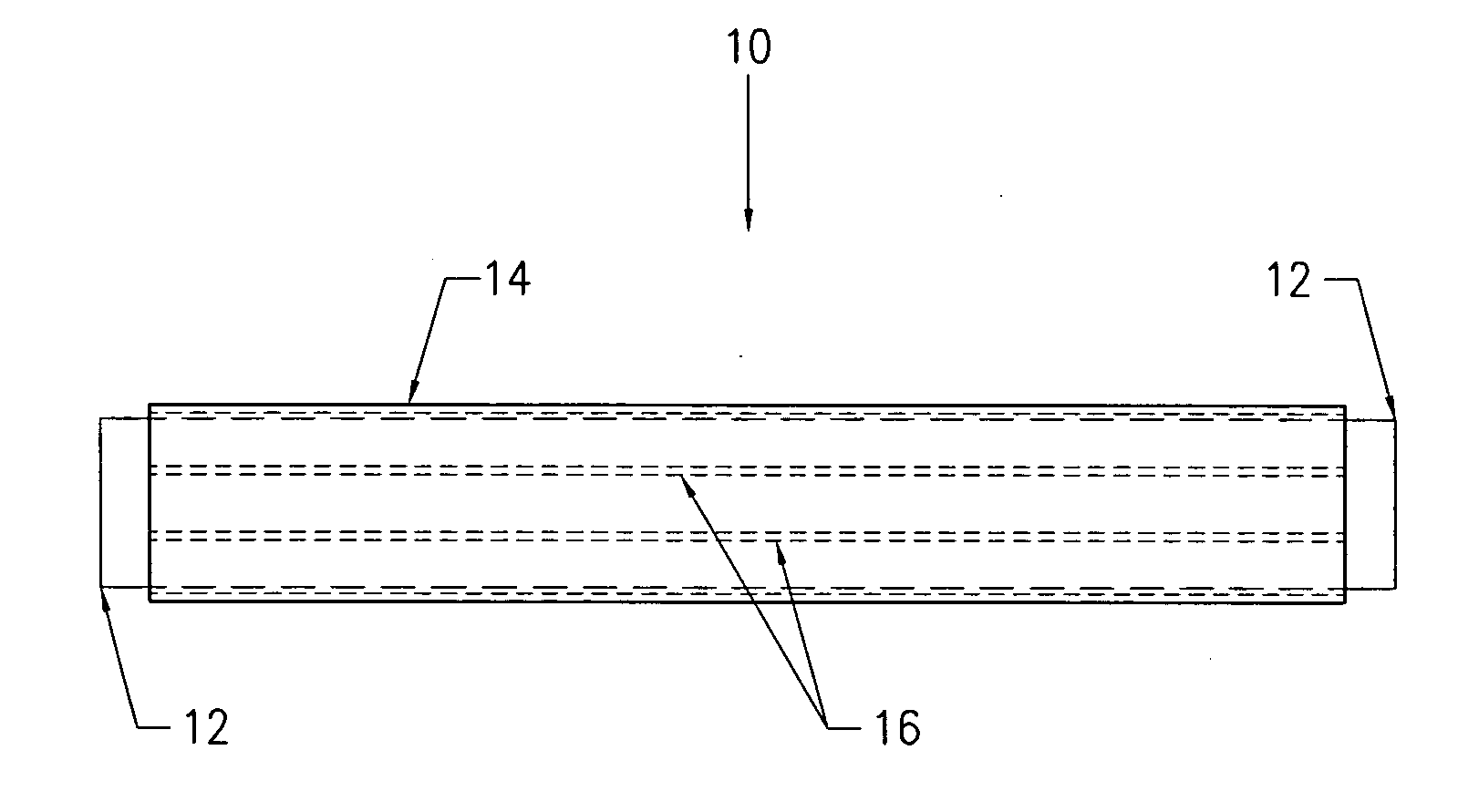
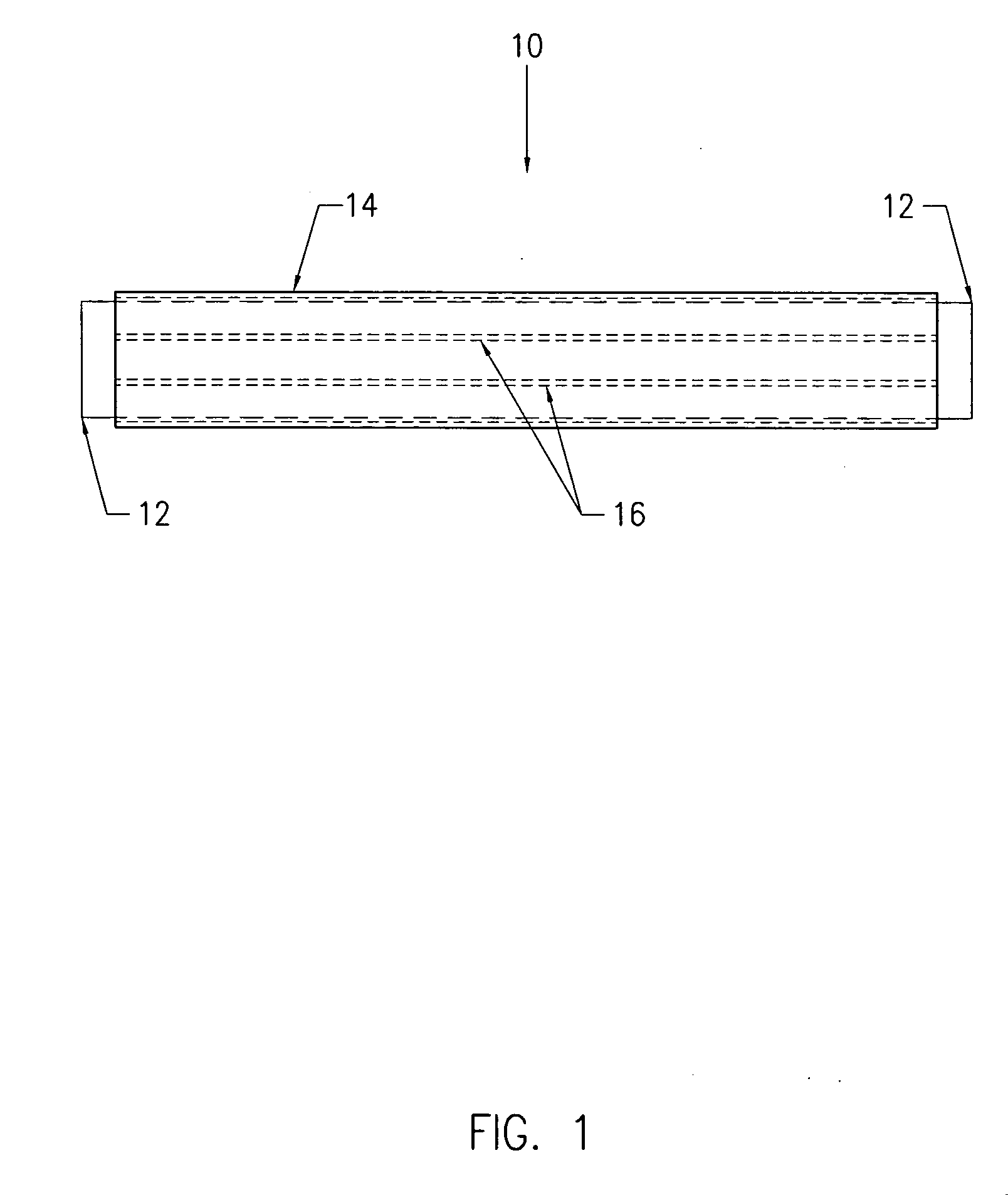
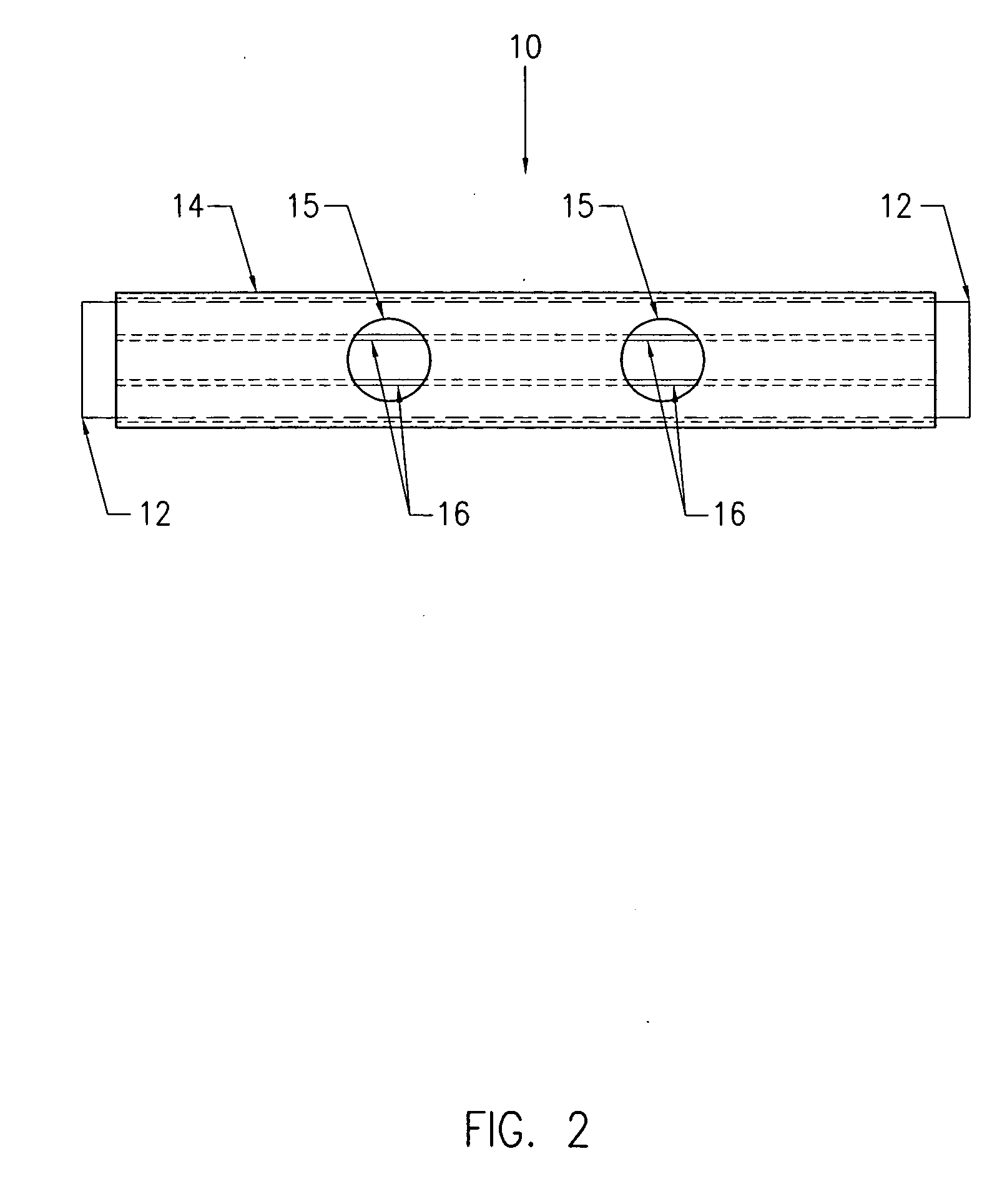
[0040] A buckling restrained structural brace assembly (BRSBA 10) is a load-bearing member (core 12) preferably surrounded by a buckling-restraining member (shell 14). An embodiment of the present invention resists applied loads primarily in the form of axial tension and compression. FIG. 1 illustrates an embodiment of the present invention. The buckling restrained structural brace assembly 10 may include a core 12 to which fins 16 are attached by welding or any other suitable method of fastening such as banding, riveting, bolting, or screwing. The fins 16 may also be integrally formed with the core 12. This core 12 and fin 16 element will expand when the BRSBA 10 is subjected to compression. The core 12 and fin 16 element are surrounded by a shell 14. In one embodiment, this shell 14 preferably substantially surrounds the core 12 and fins 16 without touching the fins 16. The shell 14 will come into contact with the fins 16 upon the core 12 being subjected to compressive load, where...


PUM


Abstract

A buckling restrained structural brace assembly including a load-bearing member and a buckling-restraining member to prevent the load-bearing member from buckling in extreme loading conditions. Fins can be attached to either the load-bearing member, where the fins are spaced apart from the buckling-restraining member by less than one inch, or the fins can be attached to the surrounding buckling-restraining member where the fins are spaced apart from the load-bearing member by less than one inch. Alternately, there may be no fins attached to the load-bearing member or to the buckling-restraining member. In such case, the load-bearing member is substantially surrounded by a buckling-restraining member to prevent the load-bearing member from buckling. The buckling-restraining member may be spaced apart from the load-bearing member by preferably a distance of less than one inch.

Description

[0001] This application claims the priority to Provisional Application No. 60 / 677854 filed on May 4, 2005BACKGROUND OF THE INVENTION [0002] The present invention relates generally to structural brace assemblies. More specifically, the present invention relates to a buckling restraining member surrounding a structural brace member subjected to axial tension and compression. [0003] The knowledge and techniques used in earthquake engineering have advanced rapidly in the last few decades. As a result, the number of casualties suffered during earthquakes has been greatly reduced. Nevertheless, observations of recent major earthquakes indicate that under performed structural elements in buildings and other structures result in a significant amount of structural and nonstructural damage, causing billions of dollars of loss in property damages and business interruptions. [0004] Structures are susceptible to large lateral displacements during severe earthquake ground motions. These displacem...

Claims


Application Information

Patent Timeline
Patent Type & Authority Applications(United States)
IPC IPC(8): A61F5/00
CPCE04C3/04E04C2003/026E04C2003/0413E04C2003/043E04H9/028E04C2003/0465E04C2003/0478E04C2003/0486E04C2003/0447E04H9/0237
Inventor QI, XIAOXUANSHEN, JIEHUA JAY
Owner QI XIAOXUAN
Learn More