Electrical discharge immobilization weapon projectile having multiple deployed contacts

a technology of immobilization weapon and projectile, which is applied in the field of non-lethal weapons, can solve the problems of limited range of effectiveness of conventional taerTM devices, inability to use only one second connector, and inability to achieve the effect of high effective immobilization curren

Inactive Publication Date: 2006-11-16
PARK YONG S
View PDF6 Cites 47 Cited by
  • Summary
  • Abstract
  • Description
  • Claims
  • Application Information

AI Technical Summary

Benefits of technology

[0012] In such embodiments, spring loading may be used to assist deployment of the second contacts. Furthermore, a simple battery-operated circuit in

Problems solved by technology

Thus, these connector darts may be too close together at close targets and too far apart at distant targets.
Therefore, these conventional Taser™ devices are severely limited in their range of effectiveness which the '199 patent disclosure reported as 3 to 12 feet.
One such limitation is the use of only one second connector.
Even though the '199 constitutes a significant advance of the then existing prior art, having just one second connector incurs the risk of an ineffective shot because t

Method used


Image

  • Electrical discharge immobilization weapon projectile having multiple deployed contacts
  • Electrical discharge immobilization weapon projectile having multiple deployed contacts
  • Electrical discharge immobilization weapon projectile having multiple deployed contacts

Examples


Embodiment Construction

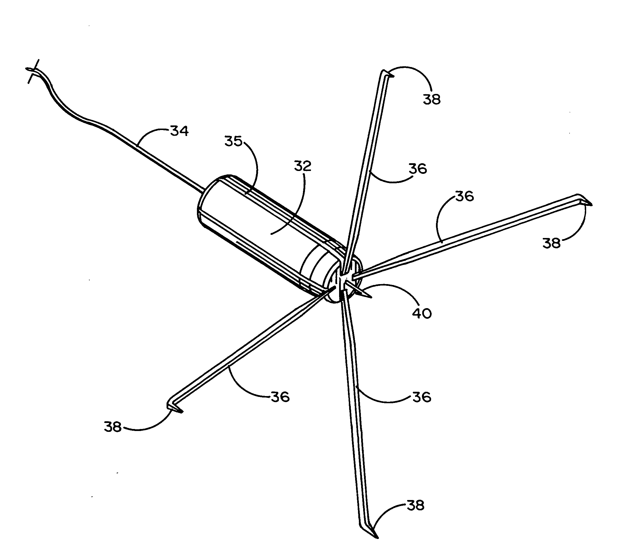
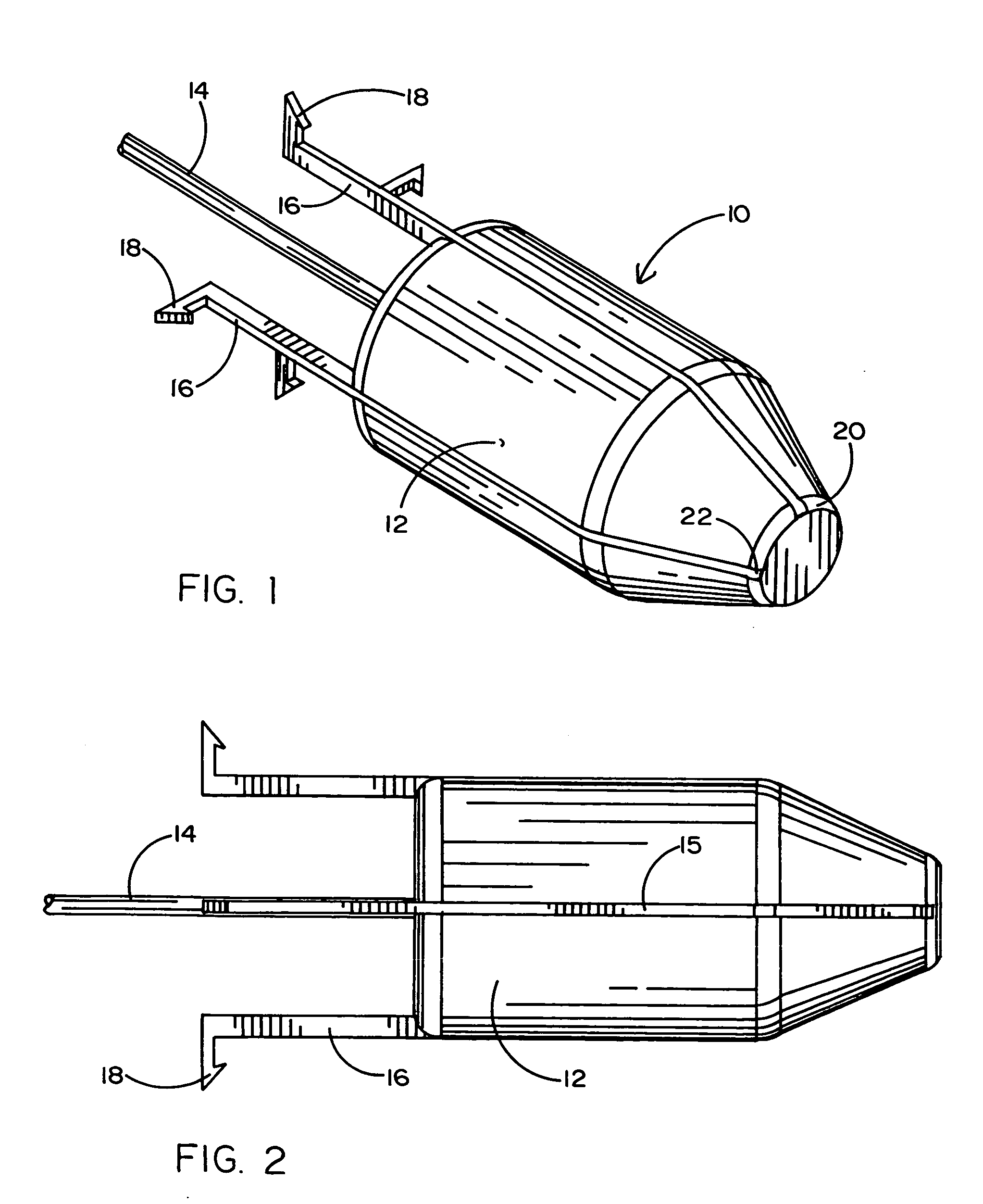
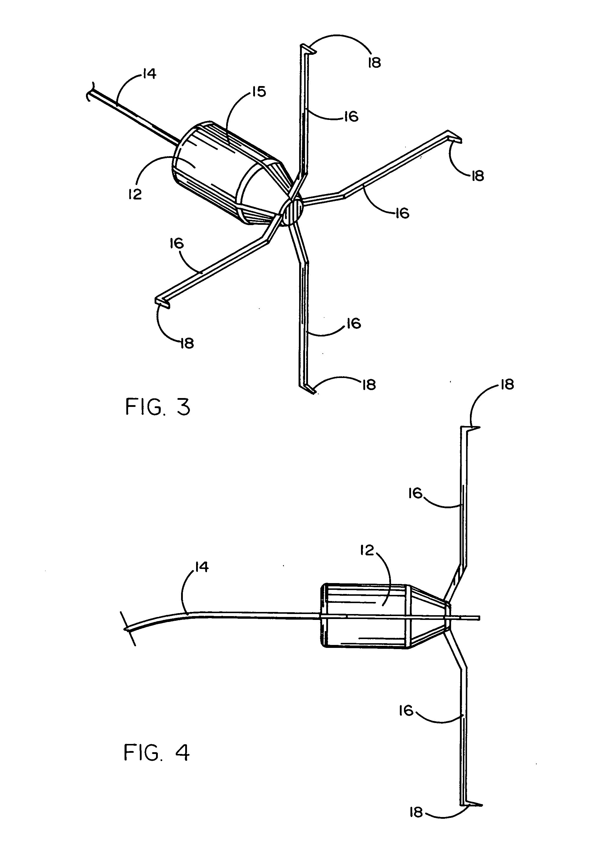
[0028] Referring first to FIGS. 1-4 and FIGS. 1 and 2 in particular, it will be seen that a first embodiment 10 comprises a projectile 12 attached to a tether cable 14 having two wires connected to opposite polarities. It will be understood that the tether cables shown herein each have a pair of well insulated electrical wires connected to a source of high voltage. Four contact arms 16 extend longitudinally along the surface of the projectile 12 in corresponding grooves 15 and extend rearwardly beyond the projectile. They are each rotatably secured at a nose portion 20 at respective fulcrums 22. The rearward ends of the arms 16 each terminate in a fleshette or barb 18. As shown best in FIGS. 3 and 4, after impact with a target, the arms 16 swing forward around their respective fulcrums 22 until the barbs 18 face forward (to contact the target) and thereby effectively “grasp” the target at multiple spaced locations.

[0029] A second embodiment 30 shown in FIGS. 5-8 is similar to the f...


PUM


Abstract

A unitary projectile for an immobilization weapon and tethered by two electrical wires, has a plurality of electrical contacts including several contacts dispersed in a spaced pattern around the projectile after target impact. The pattern of several contacts substantially increases the probability that if the projectile hits the target, an immobilization circuit through the target will be completed. The deployment of the second contacts occurs as a result of the sudden deceleration of the projectile when it impacts the target or by the use of an additional spring-biased device. This simplifies the deployment as well as the projectile configuration and likely reduces the risk of misactivation or an ill-timed activation of the second contacts. In a preferred version of the disclosed embodiments, each projectile has its own electrical contact which forms one of the two polarities of the electrical discharge. In addition, there are preferably four second polarity contacts dispersed in a symmetrical arrangement around the projectile.

Description

BACKGROUND OF THE INVENTION [0001] 1. Field of the Invention [0002] This invention relates generally to the field of non-lethal weapons for immobilizing a live target for capture and more specifically to such a weapon having a wire-tethered projectile configured for long distance usage by employing wires carrying positive and negative polarities from a high voltage source and contacts for applying the voltage across the target, the distance between the contacts on the target being substantially constant irrespective of distance to the target. [0003] 2. Prior Art [0004] This invention is intended as an improvement over the invention disclosed in previously issued U.S. Pat. No. 5,831,199 to McNulty, Jr. et al. That prior art patent discloses an immobilization weapon which employs a projectile launched toward a remote target and having two connectors for applying a high voltage discharge across spaced locations on the target. A key innovation of that invention is the use of a first con...

Claims


Application Information

Patent Timeline
IPC IPC(8): F41C9/00H01T23/00
CPCF41H13/0025H05C1/06F42B12/54
Inventor PARK, YONG S.
Owner PARK YONG S
Why Eureka
Try Eureka