Geared motor

Active Publication Date: 2006-11-16
DENSO CORP
View PDF19 Cites 18 Cited by
  • Summary
  • Abstract
  • Description
  • Claims
  • Application Information

AI Technical Summary

Benefits of technology

[0014] According to one aspect of the present invention, there is provided a geared motor that includes a motor arrangement and a speed reducing arrangement, which are assembled together. The speed reducing arrangement reduces a rotational speed of the motor arrangement and includes a housing, a support shaft, a worm wheel, a rotation transmitting member, an output gear and an annular seal member. The support shaft is secured to the housing. The worm wheel is rotatably supported by the support shaft and reduces the rotational speed of the motor arrangement. The rotation transmitting member includes a receiving through hole, which has an inner diameter larger than an outer diameter of the support shaft and receives the support shaft therethrough. The rotation transmitting member is engageable with the worm wheel to rotate integrally with the worm wheel upon receiving a rotational drive force from the worm wheel. The output gear is engageable with the rotation transmitting member to ro

Problems solved by technology

Thus, the water, which is applied between the output gear and the support shaft or between the output gear and the transmission plate is limited from moving further into the interior of the gear housing.
However, when the applied amount of grease is excessively large, the excessive amount of grease has no place to move.
Thus, the excessive amount of grease may possibly push the O-ring out of the receiving recess.
Then, the pinched portion of the O-ring may be cut to cause a trouble.
In c

Method used


Image

  • Geared motor
  • Geared motor
  • Geared motor

Examples


Embodiment Construction

[0024] One embodiment of the present invention will be described with reference to the accompanying drawings.

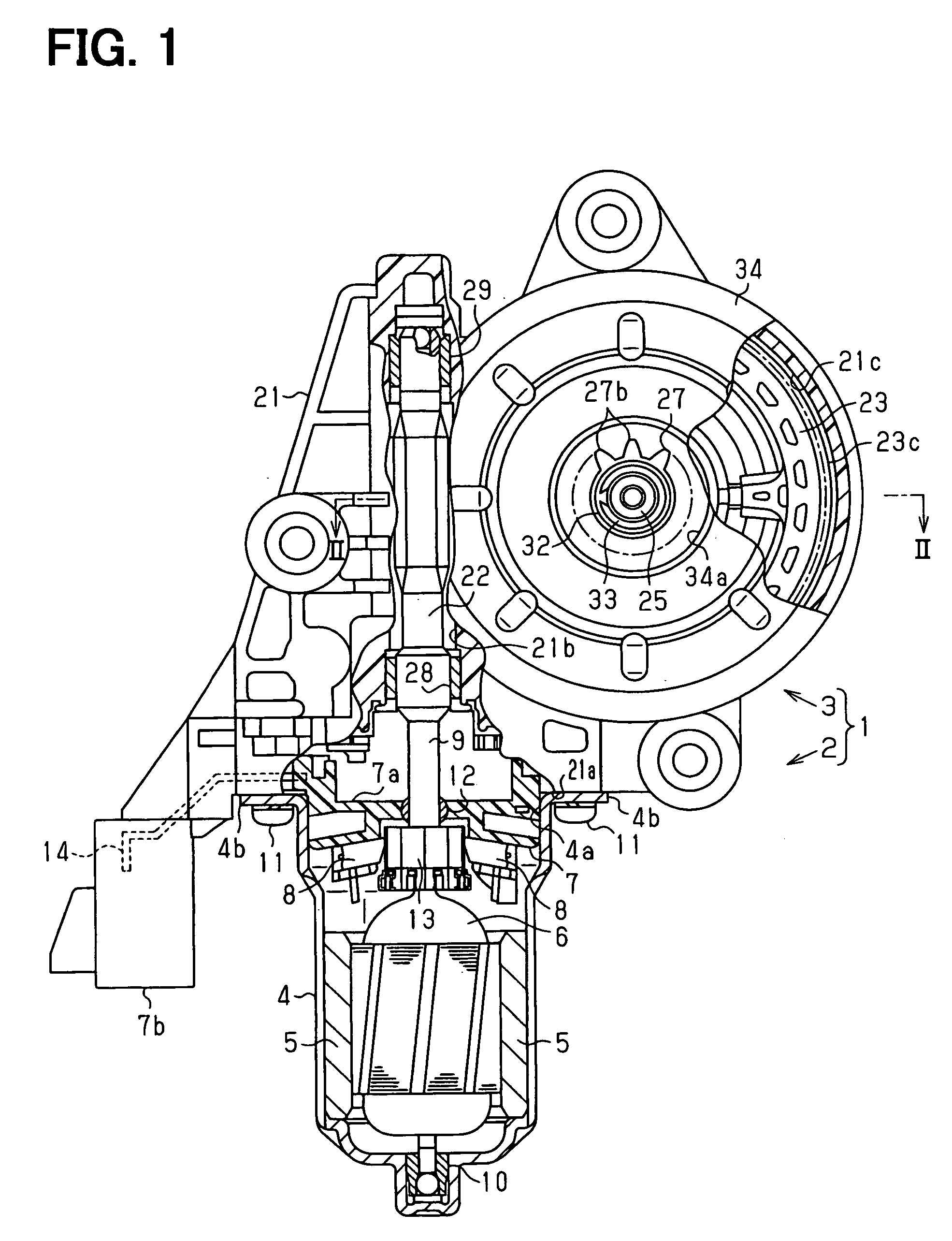
[0025]FIG. 1 shows a geared motor 1 according to the present embodiment. The geared motor 1 is a motor that is used as a drive power source of, for example, a power window system installed in a vehicle. The geared motor 1 includes a motor arrangement 2 and a speed reducing arrangement 3.

[0026] The motor arrangement 2 includes a yoke housing 4, two magnets 5, an armature 6, a brush holder 7 and two brushes 8.

[0027] The yoke housing 4 is made from a magnetic metal plate material, which is pressed into a generally flat cup shaped body. The magnets 5 are secured to an inner peripheral surface of the yoke housing 4. The armature 6 is placed radially inward of the magnets 5 in the yoke housing 4 in a manner that allows rotation of the armature 6. The armature 6 includes a rotatable shaft 9. A base end of the rotatable shaft 9 is rotatably supported by a bearing 10, which is inst...


PUM


Abstract

In a geared motor, a worm wheel, an O-ring, a transmission plate and an output gear are installed to a support shaft. The O-ring is placed in an inner space of a receiving through hole of the transmission plate, through which the support shaft is received. Grease is applied to an outer peripheral surface of the support shaft. A grease relief passage, which relieves the grease, extends between the output gear and the transmission plate.

Description

CROSS REFERENCE TO RELATED APPLICATION [0001] This application is based on and incorporates herein by reference Japanese Patent Application No. 2005-141732 filed on May 13, 2005. BACKGROUND OF THE INVENTION [0002] 1. Field of the Invention [0003] The present invention relates to a geared motor that has a motor arrangement and a speed reducing arrangement. [0004] 2. Description of Related Art [0005] A geared motor, such as one recited in Japanese Unexamined Patent Publication No. 2002-106649 (corresponding to U.S. Pat. No. 6,481,306 B2), is used as a drive power source of, for example, a power window system. In the above geared motor, a rotational speed of a rotatable shaft of a motor arrangement is reduced by a worm wheel of a speed reducing arrangement and is then transmitted to an output gear to drive a window regulator, which lowers and raises a window glass. [0006] In the structure for transmitting the rotation from the worm wheel to the output gear, the worm wheel is rotatably ...

Claims


Application Information

Patent Timeline
IPC IPC(8): F16H1/16B60J1/17B60J5/00E05F15/14F16H57/02F16H57/04H02K5/10H02K7/116
CPCF16H1/16F16H57/0463Y10T74/19828Y10T74/19991F16H57/0498
Inventor OTA, AKIRATSUDA, HIROKAZU
Owner DENSO CORP
Why Eureka
Try Eureka