
Bypass duct boss repair technology

Active Publication Date: 2006-11-16
HONEYWELL INT INC
View PDF16 Cites 6 Cited by
  • Summary
  • Abstract
  • Description
  • Claims
  • Application Information

AI Technical Summary

Problems solved by technology

During operation of the gas turbine engine, the boss / bypass duct assembly may experience various stresses.
Moreover, the assembly can experience significant vibration effects both from the engine and from fluid forces as bleed air passes through the ductwork that is mounted on the boss.
Engine accelerations and decelerations may further stress the boss and bypass duct joint.
Additionally, interior portions of the bypass duct and boss assembly experience turbulent air flows and air pressures that accompany fan air.
The joint between the bypass duct and its associated boss may therefore be subject to stress failure.
After a certain degree of service, a bypass duct and boss assembly may need repair or replacement because of the above-described stresses that the assembly encounters.
The option of replacing the bypass duct with a new part is unattractive due to the potentially high expense involved.
Moreover, when a bypass duct becomes damaged, it may be that only the duct / boss interface needs to be repaired, while the structures themselves are still usable.
Further, it may be economically disadvantageous to periodically inspect a bypass duct / boss assembly for signs of cracking and diminished performance.
Inspection is time consuming, and in those cases involving high capital equipment, it can be costly and undesirable to take a vehicle out of service for inspection.

Method used


Image

  • Bypass duct boss repair technology
  • Bypass duct boss repair technology
  • Bypass duct boss repair technology

Examples


Embodiment Construction

[0016] The following detailed description of the invention is merely exemplary in nature and is not intended to limit the invention or the application and uses of the invention. Furthermore, there is no intention to be bound by any theory presented in the preceding background of the invention or the following detailed description of the invention. Reference will now be made in detail to exemplary embodiments of the invention, examples of which are illustrated in the accompanying drawings. Wherever possible, the same reference numbers will be used throughout the drawings to refer to the same or like parts.

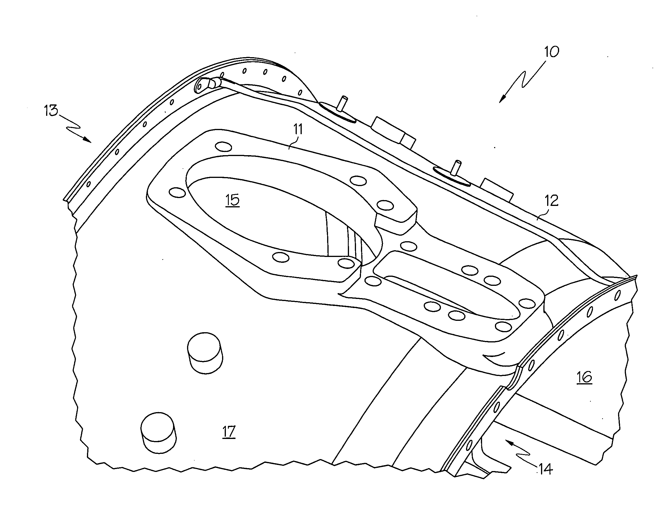
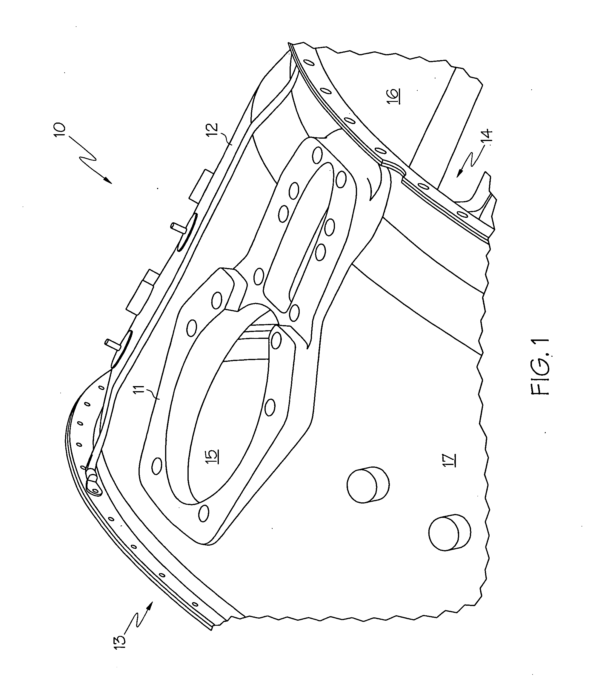
[0017] Referring now to FIG. 1 there is shown a perspective view of assembly 10 that includes boss 11 and bypass duct 12. Bypass duct 12 is typically hollow in shape and includes an interior surface 16 and exterior surface 17 that define an interior region and exterior region, respectively. As is known in the art, the gross shape of bypass duct 12 is approximately cylindrical, but ...


PUM


Abstract

The present invention provides a bypass duct and boss assembly comprising: a bypass duct having an exterior surface, an interior surface, an edge surface, an inner bonding surface, and a side wall surface, wherein the edge surface further defines an aperture; a boss having a lip surface, a side surface, and a face surface, wherein the boss is disposed within the aperture of the bypass duct such that the lip surface of the boss forms matched bonding surfaces with a portion of the exterior surface of the bypass duct, and such that the side surface of the boss forms matched bonding surfaces with the edge surface of the bypass duct; a patch having a patch edge, a patch inner surface, and a patch outer surface, wherein the patch is disposed such that the patch inner surface forms matched bonding surfaces with the inner bonding surface of the bypass duct and the face surface of the boss, and such that the patch edge forms matched bonding surfaces with the side wall surface of the bypass duct, the patch further having a thickness and curvature, and the patch further disposed such that the patch outer surface forms a continuous curvature with the interior surface of the bypass duct; and adhesive disposed between the matched bonding surfaces so as to firmly bond the bypass duct, boss, and patch into the assembly.

Description

FIELD OF THE INVENTION [0001] The present invention relates to the repair of a damaged bypass duct and boss assembly, and more particularly, relates to the use of a patch to increase the bonding strength of a repaired bypass duct and boss assembly for use with gas turbine engines. BACKGROUND OF THE INVENTION [0002] Gas turbine engines such as turbofan engines used in jet aircraft often include an assembly of a bypass duct and boss. The bypass duct provides a shell-like structure that surrounds core engine components such as the compressor stage, combustion stage, and / or turbine stage of the engine. Fan air from the turbine engine passes through the interior of the bypass duct. Engine control equipment is typically positioned on the exterior of the bypass duct. This control equipment, such as for example air bleed ducts, oil tubing, electronic control wiring, and hydraulic pressure lines, is in some designs mounted on the boss, which is in turn mounted on the bypass duct. [0003] Duri...

Claims


Application Information

Patent Timeline
IPC IPC(8): F16L55/18
CPCF01D25/243F05D2230/80Y02T50/672Y02T50/60
Inventor VINTILESCU, ION V.CHUNG, VINCENTSPOTH, KEVIN A.DALLEY, GEORGE W.
Owner HONEYWELL INT INC
Learn More