Contoured surface defueling fitting

Active Publication Date: 2006-11-16
SPOKANE STAINLESS TECH INC
View PDF6 Cites 12 Cited by
  • Summary
  • Abstract
  • Description
  • Claims
  • Application Information

AI Technical Summary

Benefits of technology

[0012] The defueling fitting facilitates safe and convenient defueling of certain aircraft that have contoured surfaces adjacent to drain valves, as well as aircraft that have flat surfaces adjacent to th

Problems solved by technology

At some point, however, most defueling systems require some type of gravity feed, resulting in low drain rates and long drain times. In fact, for many large aircraft, depending on the amount of fuel remaining in the tanks, it can take up to several hours to fully defuel the aircraft using a gravity dependent system.
Nevertheless, many vacuum assist syste

Method used


Image

  • Contoured surface defueling fitting
  • Contoured surface defueling fitting
  • Contoured surface defueling fitting

Examples


Embodiment Construction

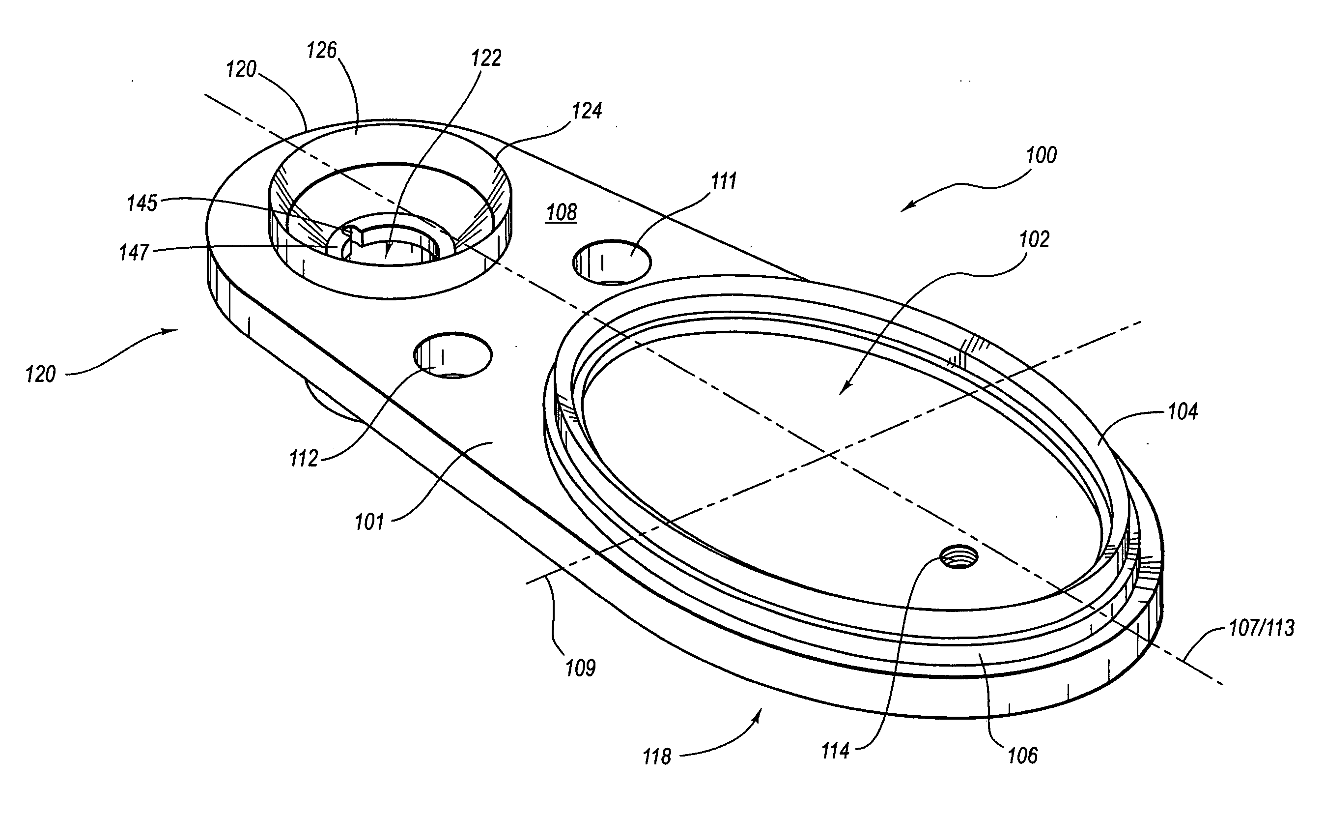
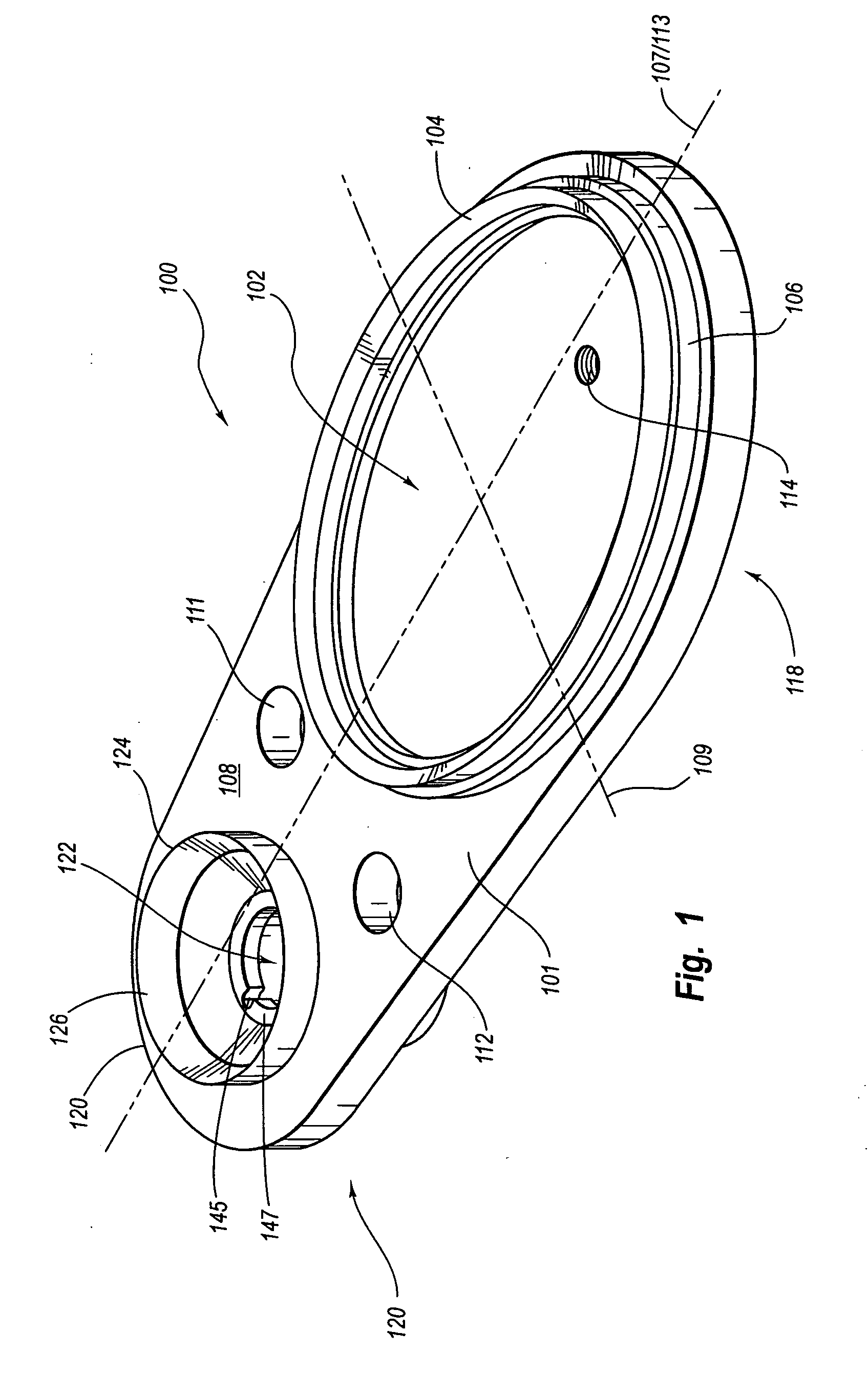
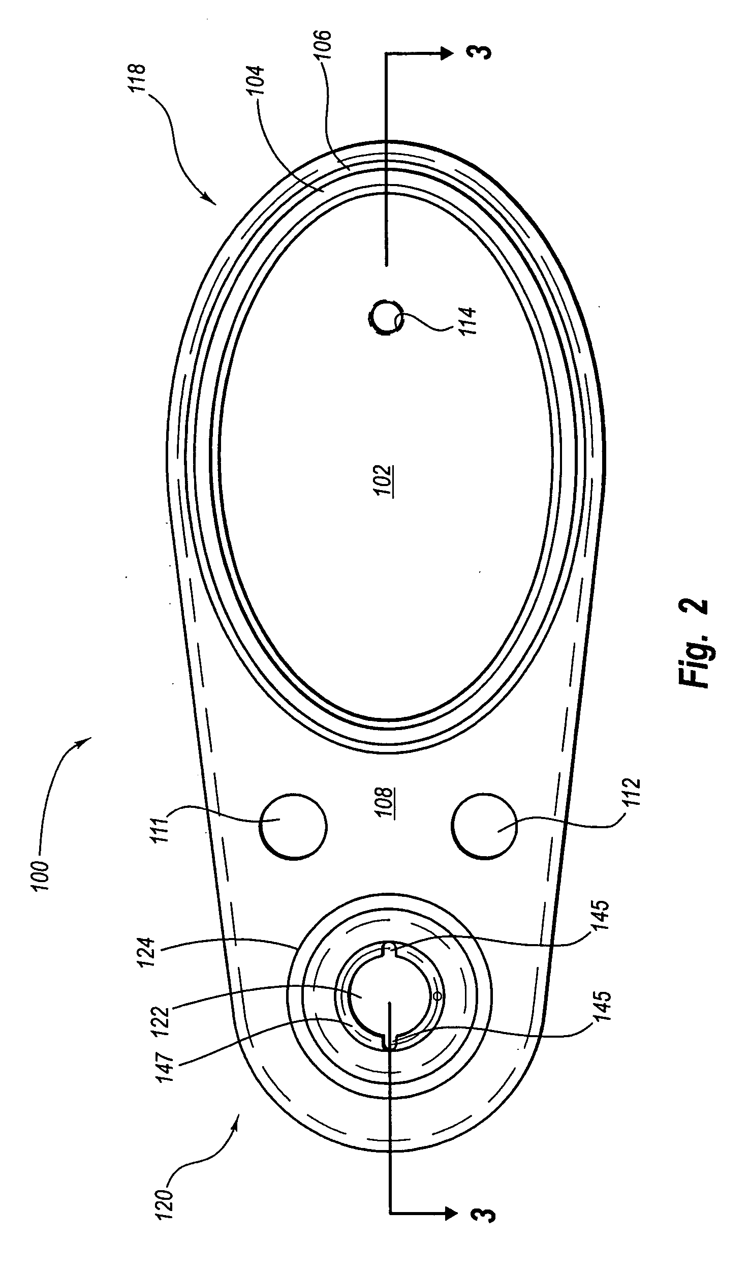
[0021] Defueling an aircraft is a common procedure prior to maintenance or repair. Most aircraft include one or more drain valves at low points of the fuel tanks to facilitate defueling. The drain valves are usually spring loaded “poppet” valves that can be opened by applying a force normal to the spring force. The drain valves of most aircraft are substantially flush with the outside body of the aircraft and therefore readily accessible with few or no local obstructions. However, some aircraft include a contoured surface adjacent to the fuel drain valve, which complicates the attachment of conventional drain fittings. Airplane wings, fuselages, and outboard removable pontoon tanks, for example, often exhibit contoured surfaces adjacent to fuel drain valves.

[0022] Therefore, the present invention contemplates aircraft defueling fittings and associated methods of defueling with features that facilitate defueling aircraft even at significantly contoured surfaces. The present inventio...


PUM


Abstract

A method and apparatus for defueling an aircraft. The apparatus includes a defueling fitting comprising one or more structural connectors, which may include one or more suction cups. The suction cups are disposed in a mount. The suction cups may be raised from a surface in the mount and arranged in a non-circular pattern to facilitate connection to contoured surfaces. An actuator assembly may be attached to the mount for opening an aircraft defueling valve. The suction cups may be operatively connected to a vacuum source to connect the defueling fitting to an aircraft body, with the actuator assembly positioned at the aircraft defueling valve. The defueling fitting facilitates safe and convenient defueling of aircraft, even aircraft with significantly contoured surfaces.

Description

FIELD OF THE INVENTION [0001] The present invention relates to aerospace equipment, and more particularly to a method and apparatus for defueling an aircraft. BACKGROUND OF THE INVENTION [0002] Aircraft often need to be defueled prior to performing certain types of maintenance or repairs. There are generally three stages of aircraft defueling: pumping (removing the majority of fuel from the aircraft fuel cells), bottom sumping (removing most of the remaining fuel from the bottom of the fuel cells—traditionally done by some type of gravity feed), and depuddling (which involves removing the small puddles remaining in the fuel cells). A number of aircraft defueling systems have traditionally been available to handle the various stages of aircraft defueling. At some point, however, most defueling systems require some type of gravity feed, resulting in low drain rates and long drain times. In fact, for many large aircraft, depending on the amount of fuel remaining in the tanks, it can ta...

Claims


Application Information

Patent Timeline
IPC IPC(8): B65B31/04
CPCB64F1/28
Inventor KUNTZ, JAMES P.
Owner SPOKANE STAINLESS TECH INC
Why Eureka
Try Eureka