Magnetic disk drive and ramp

a magnetic disk drive and ramp technology, applied in the field of magnetic disk drives, can solve the problems of reducing the most likely to be disturbed by the air stream, and the vibration of the actuator that supports the magnetic head, so as to reduce the positioning accuracy of the magnetic head

Inactive Publication Date: 2006-11-16
WESTERN DIGITAL TECH INC
View PDF11 Cites 20 Cited by
  • Summary
  • Abstract
  • Description
  • Claims
  • Application Information

AI Technical Summary

Benefits of technology

[0007] In the conventional magnetic disk drive mentioned above, however, since the shroud is provided as an element independent of a ramp, a break in the shroud at a ramp causes a disturbance in the air stream, coupled with the rotation of the magnetic disk, thus leading to vibration of the actuator that supports the magnetic head. Also, the absence of a shroud at the ramp means that the air stream is most likely to be disturbed near the magnetic head. That is to say, in addition to the vibration of the actuator, the shroud structure described above has caused the vibration of the suspension which supports the magnetic head, resulting in reduced positioning accuracy of the magnetic head.
[0008] The present invention was made with the above problems in view, and it is a feature of the invention to provide a magnetic disk drive that can effectively suppress the influence of an air stream coupled with the rotation of a magnetic disk.

Problems solved by technology

In the conventional magnetic disk drive mentioned above, however, since the shroud is provided as an element independent of a ramp, a break in the shroud at a ramp causes a disturbance in the air stream, coupled with the rotation of the magnetic disk, thus leading to vibration of the actuator that supports the magnetic head.
Also, the absence of a shroud at the ramp means that the air stream is most likely to be disturbed near the magnetic head.
That is to say, in addition to the vibration of the actuator, the shroud structure described above has caused the vibration of the suspension which supports the magnetic head, resulting in reduced positioning accuracy of the magnetic head.

Method used


Image

  • Magnetic disk drive and ramp
  • Magnetic disk drive and ramp
  • Magnetic disk drive and ramp

Examples


Embodiment Construction

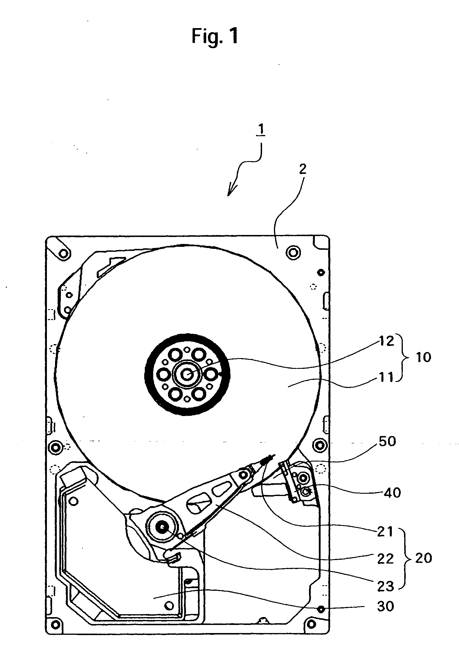
[0016] A magnetic disk drive according to an embodiment of the present invention will be described below with reference to the accompanying drawings. FIG. 1 is a top view that shows major constituent elements of the magnetic disk drive of the present embodiment.

[0017] As shown in FIG. 1, various members of magnetic disk drive 1 are installed in or on a base 2 which is part of an enclosure. During mounting, a cover not shown is installed over the base 2 to hermetically seal the enclosure.

[0018] The magnetic disk drive 1 has a disk assembly 10 that includes at least one magnetic disk medium 11 onto which data will be written, and the disk assembly is pivotally held by a spindle motor 12.

[0019] A case in which the disk assembly 10 has two magnetic disk media 11 in the present embodiment is taken as an example in the description thereof. Hereinafter, when the two magnetic disk media 11 included in the disk assembly 10 are to be called distinctly, the upper of the two magnetic disk me...


PUM

PropertyMeasurementUnit
magneticaaaaaaaaaa
radius of curvatureaaaaaaaaaa
thicknessaaaaaaaaaa

Abstract

Embodiments of the invention provide a magnetic disk drive that can effectively suppress the influence of an air stream coupled with the rotation of a magnetic disk. In one embodiment, the magnetic disk drive is adapted to have a disk assembly that includes at least one magnetic disk medium, a head assembly that includes at least one magnetic head which writes magnetic signals onto and reads them out from the magnetic disk medium or media, and at least one arm which supports the magnetic head(s), a ramp assembly that includes at least one ramp which guides the magnetic head(s) to a required retreat position(s) when the particular magnetic head is moved away from the associated magnetic disk medium, and shroud fins as many in number as the magnetic disk media, in which case, each shroud fin is disposed integrally with the ramp assembly and in association with and next to either of the magnetic disk media in order to guide an air stream produced by the rotation of the disk assembly.

Description

CROSS-REFERENCES TO RELATED APPLICATIONS [0001] This application claims priority from Japanese Patent Application No. JP2005-136964, filed May 10, 2005, the entire disclosure of which is incorporated herein by reference. BACKGROUND OF THE INVENTION [0002] The present invention relates to magnetic disk drives, and more particularly, to a ramp for storing a magnetic head. [0003] The types of operation schemes of magnetic disk drives such as hard-disk drives include the so-called load / unload scheme. In this scheme, the magnetic disk drive glides a magnetic head to a position above a desired sector on the magnetic disk when conducting a process such as writing data onto a magnetic disk or reading out data therefrom, and moves the magnetic head away from the magnetic disk when not conducting the process. [0004] The magnetic disk drives employing the load / unload scheme to have a ramp along which the magnetic drive guides the magnetic head to a required retreat position when moving the hea...

Claims


Application Information

Patent Timeline
Patent Type & Authority Applications(United States)
IPC IPC(8): G11B5/54
CPCG11B21/22G11B5/48
Inventor HAYAKAWA, TAKAKO
Owner WESTERN DIGITAL TECH INC
Why Eureka
Try Eureka