Double side polishing method and apparatus

Inactive Publication Date: 2010-01-19
SUMITOMO MITSUBISHI SILICON CORP
View PDF16 Cites 19 Cited by
  • Summary
  • Abstract
  • Description
  • Claims
  • Application Information

AI Technical Summary

Benefits of technology

[0071]According to this wafer transfer and loading apparatus, the outer-circumference circular sucking chuck comes in contact with the bottom surface of the wafer but the contact area of the wafer is limited to its periphery. No device is normally fo

Problems solved by technology

Since a plurality of carriers are conventionally placed on the lower surface plat

Method used


Image

  • Double side polishing method and apparatus
  • Double side polishing method and apparatus
  • Double side polishing method and apparatus

Examples


Embodiment Construction

[0099]Preferred embodiments of a double side polishing apparatus according to the present invention will be described with reference to FIGS. 1 to 11.

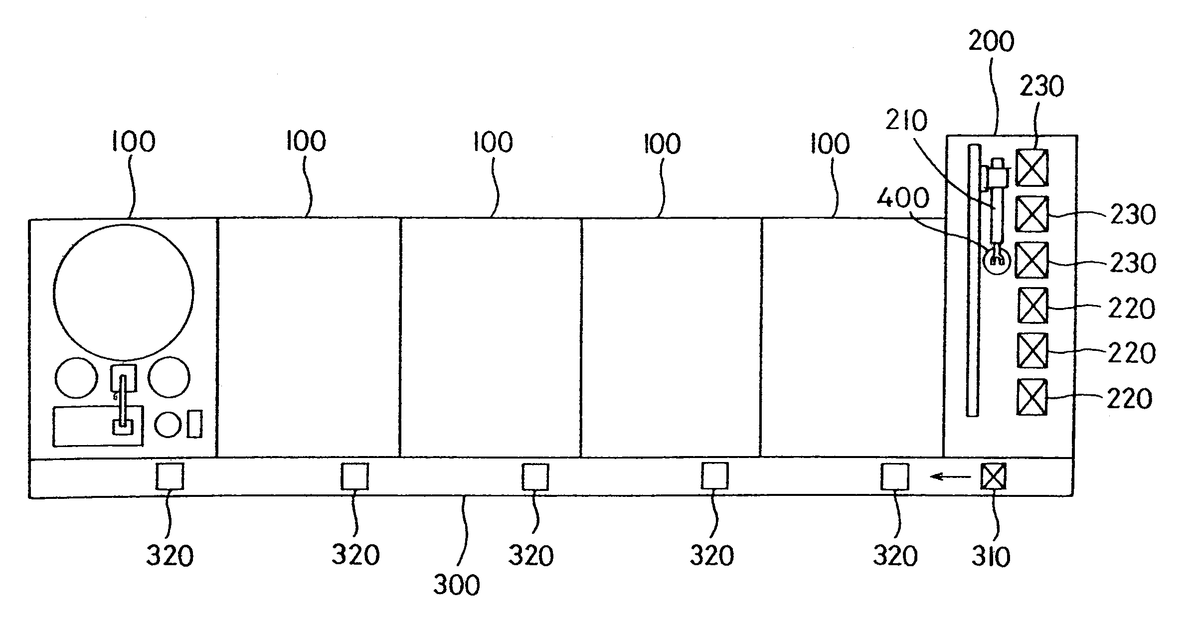
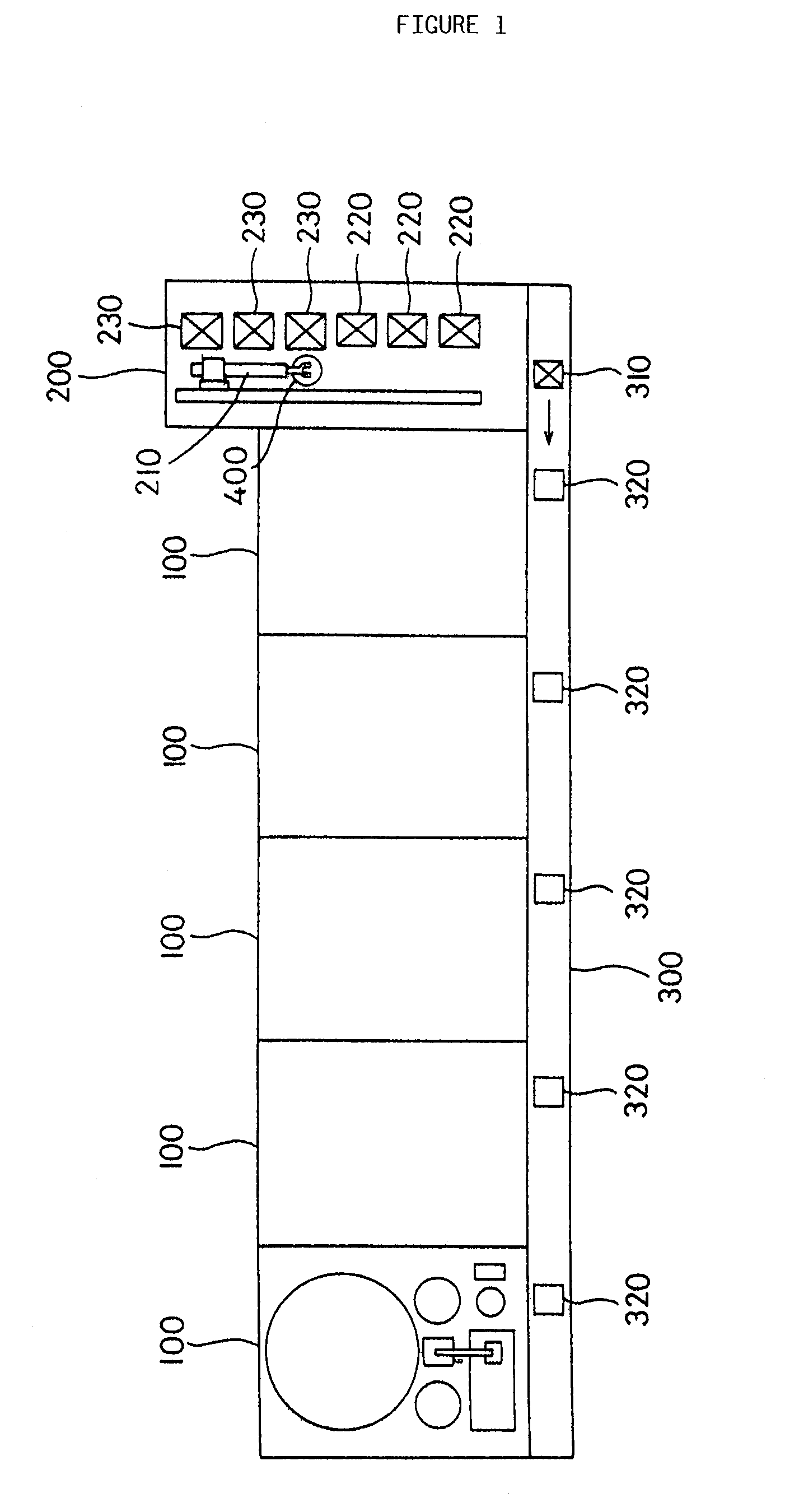
[0100]The double side polishing apparatus shown in FIG. 1 is used for automated double side polishing of silicon wafers. This double side polishing facility comprises a plurality of double side polishing apparatuses 100, 100, . . . arranged in a lateral direction of the facility, a loader unloader apparatus 200 arranged at a side of the double side polishing apparatuses, and a basket conveying apparatus 300 joining these apparatuses together.

[0101]The loader unloader apparatus 200 comprises a sucking type work conveying robot 210. The sucking type work conveying robot 210 picks out an unpolished work 400 comprising a silicon wafer from a loading basket 220, and transfers and loads it in a conveying basket 310 in the basket conveying apparatus 300. In addition, the sucking type work conveying robot 210 picks out a polished work 400 from...


PUM


Abstract

A method of polishing the double sides of a plurality of works simultaneously by rotating a plurality of carriers between upper and lower rotating surface plates, comprising the steps of forming the works (400) integrally with the carriers (500) on the outside of a polishing device main body (110), feeding the works (400) onto a rotating surface plate (111) on the underside of the polishing device main body (110) with the works formed integrally with the carriers (500), injecting liquid such as water from the upper side rotating surface plate when the upper side rotating surface plate is raised after the double sides are polished, holding the plurality of works (400) on the lower side rotating surface plate (111) after the double sides are polished, enabling the works (400) to be discharged automatically from the lower side rotating surface plate (111), providing a brush storage part (180) and a dresser storage part (190) near the polishing device main body (110), and frequently treating a polishing cloth installed on the opposed surfaces of the upper and lower rotating surface plates with a brush and a dresser.

Description

TECHNICAL FIELD[0001]The present invention relates to a double side polishing method and apparatus for use in, for example, double side polishing of a silicon wafer.BACKGROUND ART[0002]A silicon wafer, which is a material of a semiconductor device, is cut out from a silicon single crystal, lapped, and then polished so as to have a mirror surface. This mirror finish was provided only on a device formation surface, but for wafers of a large diameter exceeding 8 inches, for example, 12-inch wafers, there has been a need to finish them in such a manner that their rear surface, on which no device is formed, is comparable to a mirror one. It has correspondingly been necessary to polish both surfaces of the wafers.[0003]A planetary gear-based double side polishing apparatus is normally used for double side-polishing of a silicon wafer. The structure of this double side polishing apparatus will be described in brief with reference to FIGS. 26 and 27. FIG. 27 is taken along a line C-C in FIG...

Claims


Application Information

Patent Timeline
IPC IPC(8): B24B1/00B24B7/17B24B37/08B24B41/00B24B53/007B24B53/017
CPCB24B7/17B24B37/08B24B41/005B24B53/017
Inventor HORIGUCHI, AKIRAISOBE, KENTANAKA, HEIGOFUKUSHIMA, TOMIOMURATA, KIYOHIDETAKEDA, TSUNCOUZU, YOSHIAKIMATSUMOTO, HIROSHI
Owner SUMITOMO MITSUBISHI SILICON CORP
Why Eureka
Try Eureka