Numerical control apparatus and numerical control system

a numerical control system and control apparatus technology, applied in the direction of electric programme control, program control, instruments, etc., can solve the problems of position accuracy degradation, noise generation, positional errors,

Active Publication Date: 2006-06-22
MITSUBISHI ELECTRIC CORP +1
View PDF8 Cites 20 Cited by
  • Summary
  • Abstract
  • Description
  • Claims
  • Application Information

AI Technical Summary

Benefits of technology

[0009] It is an object of the present invention to at least solve the problems in the conventional technology.

Problems solved by technology

Although the clamp apparatus enhances the rigidity, its presence can cause a positioning accuracy of the shaft to degrade.
If the shaft is positioned with the servomotor in a non-clamping state,.and if the shaft is clamped with a clamp apparatus, problems such as generation of noises due to a meshing error or hitting of teeth to each other can occur.
In the conventional technique, however, only a positional error (angular error) in a moving direction of the clamp shaft (a pivot shaft of the tool rest) that occurs due to a difference between the clamping state and the non-clamping state is set as an object to be corrected.
In fact, although very small, positional errors occur even in other directions (for example, an axial direction of the pivot shaft) due to the difference between the clamping state and the non-clamping state.
In the conventional technique, the positional error in the other moving directions can not be corrected.
In the conventional technique, however, there is a problem that the position of the tool cannot be controlled with a high accuracy neither in the clamping state nor in the non-clamping state.

Method used


Image

  • Numerical control apparatus and numerical control system
  • Numerical control apparatus and numerical control system
  • Numerical control apparatus and numerical control system

Examples


first embodiment

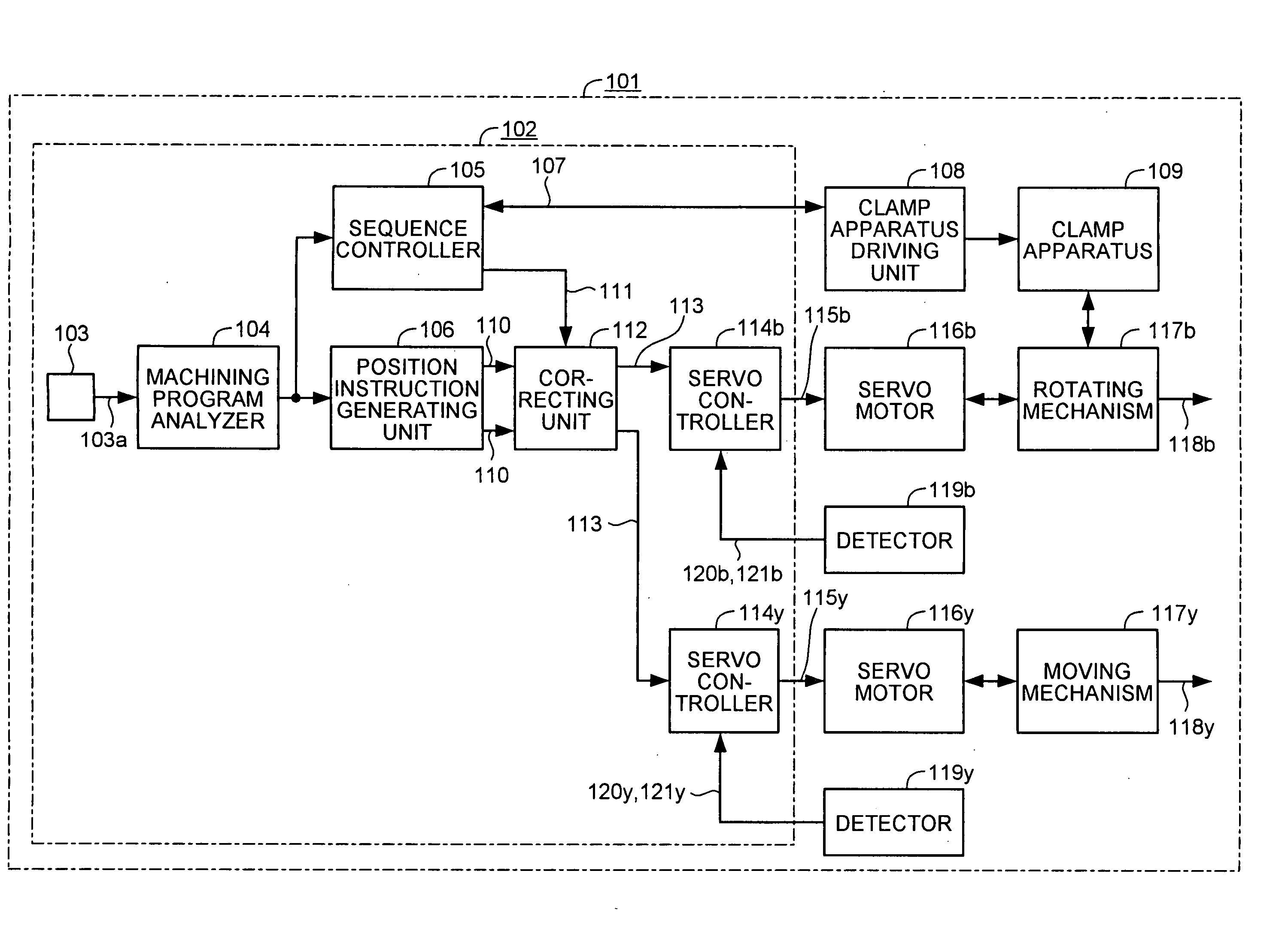
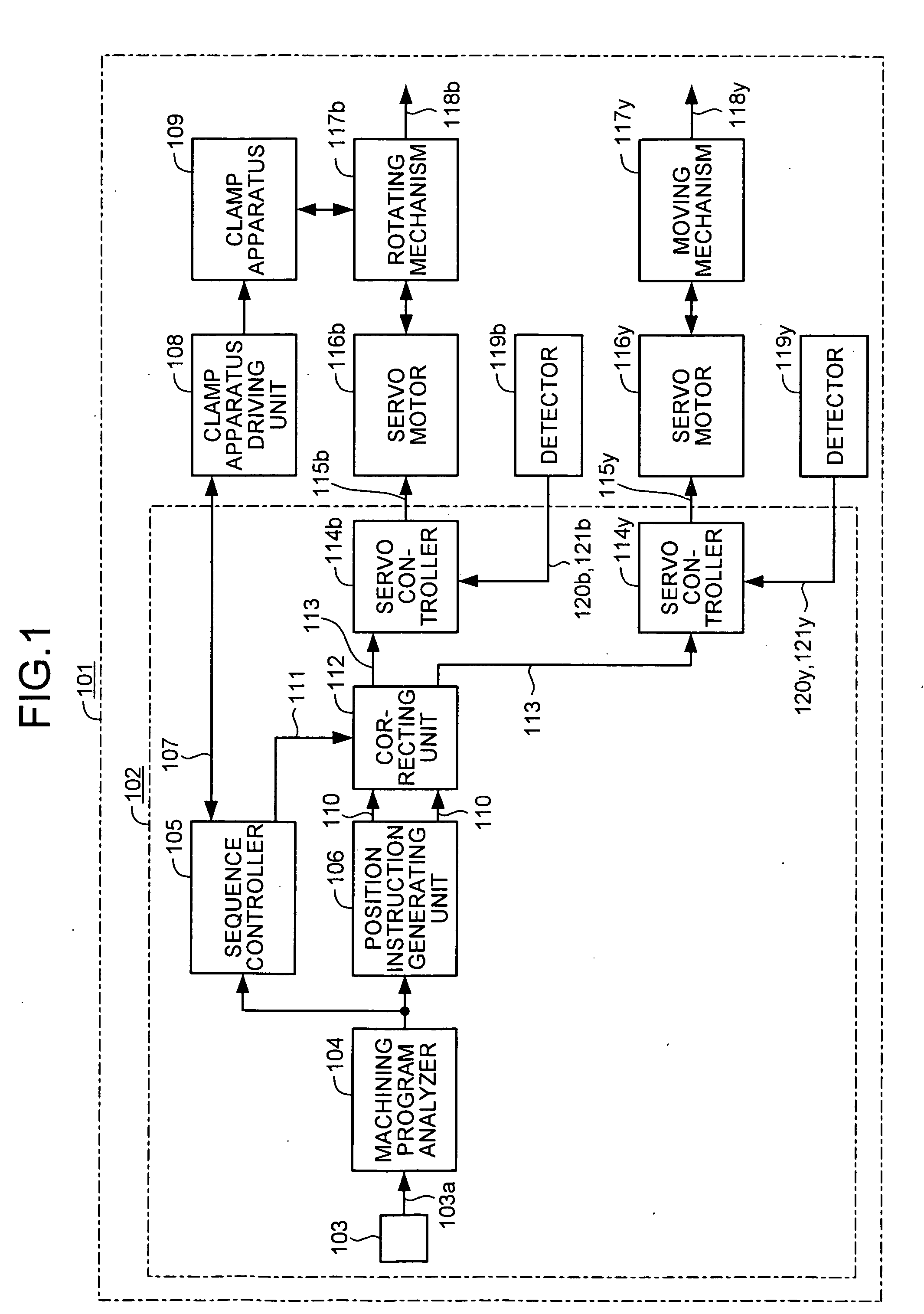
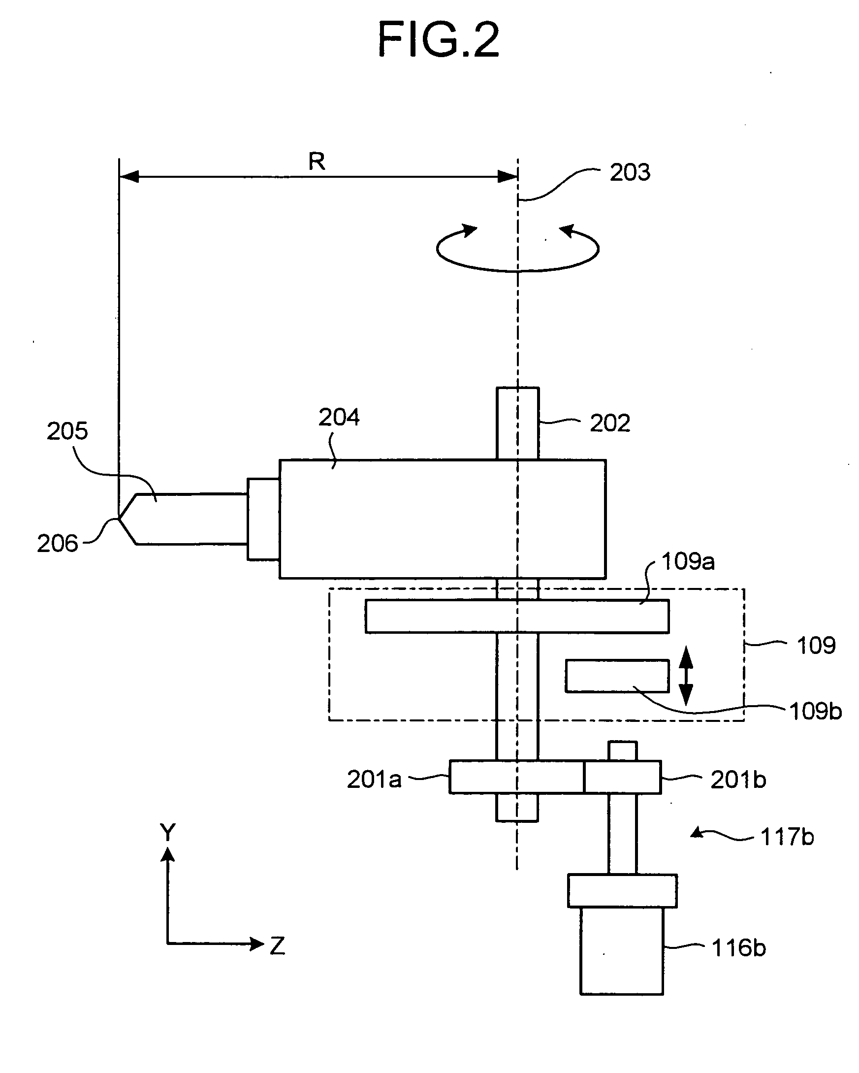
[0020]FIG. 1 is a block diagram of a schematic configuration of an NC system 101 that includes an NC apparatus 102 according to the present invention, and FIG. 2 is a schematic diagram of a driving mechanism for a tool rest in the NC system 101.

[0021] The NC system 101 is a machine tool, which, in the simplest constitution, includes two shafts: one shaft (B-axis) 202 having a clamp apparatus 109 and another shaft (Y-axis (not shown)).

[0022] The NC system 101 includes, apart from the NC apparatus 102, a B-axis servomotor 116b whose driving is controlled by the NC apparatus 102 to rotate a tool rest 204 serving as a machining head around a B-axis, a Y-axis servomotor 116y whose driving is controlled by the NC apparatus 102 to move the tool rest 204 in a Y-axis direction, a rotating mechanism 117b that include a decelerator 201b and a decelerator 201a and transmits rotation of the B-axis servomotor 116b to the tool rest 204 to rotate it, a moving mechanism 117y that converts rotation ...

second embodiment

[0041]FIG. 5 depicts a configuration of a correcting unit 212 according to the invention. The correcting unit 212 can be used in the NC apparatus 102 shown in FIG. 1 in place of the correcting unit 112. The correcting unit 212 includes a clamp correcting unit 501 and a non-clamp correcting unit 502. When in a clamping state, the clamp correcting unit 501 calculates a correction position instruction value 113 from the clamp state signal 111. When in a non-clamping state, the non-clamp correcting unit 502 calculates a correction position instruction value 113 from the clamp state signal 111.

[0042] A correcting unit 312 shown in FIG. 6 can be used in the NC apparatus 102 shown in FIG. 1 in place of the correcting unit 112. The correcting unit 312 includes a clamp correction value calculating unit 601 serving as the clamp correcting unit and a non-clamp correction value calculating unit 602 serving as the non-clamp correcting unit. When in a clamping state, the clamp correction value ca...

third embodiment

[0047] It is assumed above that there are two shafts: one shaft (B-axis) attached with the clamp apparatus 109 and another shaft (Y-axis). However, there can be three shafts as in a

[0048] In the configuration shown in FIG. 6, for example, a specific example for obtaining correction values 603 in a machine tool including one shaft (B-axis) having the clamp apparatus 109 and other three orthogonal shafts (X-axis, Y-axis, and Z-axis) is explained. Since the clamp shaft (B-axis) itself is uncontrollable in the clamping state, instead, a correction error generated at a machining position (a tool tip) 206 (see FIG. 2) due to a position error ΔB in a displacement direction of the clamp shaft is corrected using a shaft except for the clamp shaft, particularly a straight shaft. Specifically in this case, straight shafts (here, two straight shafts of an X-axis and a Z-axis perpendicular to the B-axis) corresponding to displacement directions for canceling an error in a translational position ...


PUM


Abstract

An NC apparatus controls a position of a tool by driving a plurality of shafts with a plurality of servomotors. The shafts includes at least one clamp shaft that can be mechanically clamped or non-clamped. A clamp determining unit determines whether a state of the clamp shaft and outputs a signal based on the state. A correcting unit corrects a position instruction value or a position detection value of at least one shaft other than the clamp shaft based on the signal and a correction value so as to cancel an error in a position of the tool due to movement of the tool performed by the clamp shaft.

Description

BACKGROUND OF THE INVENTION [0001] 1. Field of the Invention [0002] The present invention relates to a numerical control apparatus (hereinafter, “NC apparatus”) and a numerical control machine tool (hereinafter, “NC system”), and in particular to an NC apparatus that can control a machine tool having a shaft (hereinafter, “clamp shaft”) capable of performing clamping, and an NC system that includes the NC apparatus. [0003] 2. Description of the Related Art [0004] An NC system controls driving of servomotors having a plurality of shafts with a servo control apparatus to control movement of a tool relative to a workpiece, thereby machining the workpiece. The tool needs to be held rigidly while the machining is on its way. The tool is in generally held rigidly by the shafts of the servomotors. However, to enhance the rigidity, a clamp apparatus that can mechanically fix a position of a shaft, such as a coupling of a meshing type, is used. The clamp apparatus is used on a shaft where a ...

Claims


Application Information

Patent Timeline
Patent Type & Authority Applications(United States)
IPC IPC(8): G06F19/00G05B19/404
CPCG05B19/19G05B2219/49135
Inventor SATO, TOMONORIHAYASHI, EIJIMIZUKAMI, YUJIMURAKI, TOSHIYUKIISEKI, AKIRA
Owner MITSUBISHI ELECTRIC CORP
Why Eureka
Try Eureka