Inductive position detection configuration for indicating a measurement device stylus position

a technology of inductive position and configuration, applied in the field of precision metrology, can solve the problems of insufficient accuracy of lvdt's and other known inductive type sensors used in cmm probes, large size or awkward integration, and inability to provide reasonable levels of accuracy, etc., to achieve robust and highly accurate three-dimensional position indications, limited position determination accuracy, and sufficient application accuracy

Active Publication Date: 2020-05-07
MITUTOYO CORP
View PDF0 Cites 21 Cited by
  • Summary
  • Abstract
  • Description
  • Claims
  • Application Information

AI Technical Summary

Benefits of technology

[0032]Previously known inductive sensors utilizing nominally planar sensing elements have been far too inaccurate for application in precision scanning probes. In contrast, inductive sensors utilizing nominally planar sensing elements configured according to the various principles disclosed and claimed herein provide a robust set of signals and may be used to provide sufficient accuracy for application in precision scanning probes. In particular, implementations and / or configurations such as those outlined above may provide signal components that are particularly advantageous with regard to eliminating or allowing correction of certain signal errors and / or signal cross coupling errors that have previously limited the accuracy of position determination in known economical three-dimensional position indicators based on inductive sensing. In various implementations according to the various principles disclosed and claimed herein, the signal components that are provided by the various receiver coils are particularly advantageous in that they may be processed using relatively fast and simple signal processing in order to provide robust and highly accurate three-dimensional position indications.

Problems solved by technology

However, LVDT's and other known inductive type sensors that are sufficiently accurate for use in CMM probes may be rather large or awkward to incorporate, and the associated motion mechanisms and / or displacement detector arrangements may be relatively expensive and / or susceptible to various “cross coupling” errors (e.g., due to the general configuration and / or mechanism and / or detector imperfections, etc.).
However, the configurations disclosed in the '966 patent have several design deficiencies relative to providing the accuracy and / or form factors necessary for successful adaptation for use in a CMM scanning probe.
In short, the configurations of the '966 patent lack the sophistication and features necessary for providing reasonable levels of accuracy in modern metrology instruments such as a CMM probe.
Other issues associated with the use of known inductive sensing systems such as those outlined above in a CMM probe may include signal / response non-linearities that are inherent in the displacement response of the system, position errors resulting from less than perfect assembly and alignment, and signal drift due to environmental effects on mechanical and electrical components (e.g., due to temperature changes, etc.).

Method used


Image

  • Inductive position detection configuration for indicating a measurement device stylus position
  • Inductive position detection configuration for indicating a measurement device stylus position
  • Inductive position detection configuration for indicating a measurement device stylus position

Examples


Embodiment Construction

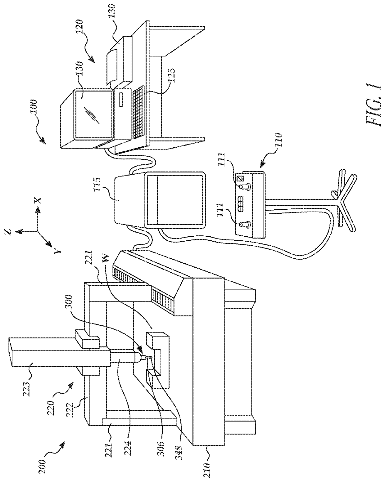
[0044]FIG. 1 is a diagram showing various typical components of a measuring system 100 including a CMM 200 utilizing a scanning probe 300 such as that disclosed herein. The measuring system 100 includes an operating unit 110, a motion controller 115 that controls movements of the CMM 200, a host computer 120 and the CMM 200. The operating unit 110 is coupled to the motion controller 115 and may include joysticks 111 for manually operating the CMM 200. The host computer 120 is coupled to the motion controller 115 and operates the CMM 200 and processes measurement data for a workpiece W. The host computer 120 includes input means 125 (e.g., a keyboard, etc.) for inputting, for example, measurement conditions, and output means 130 (e.g., a display, printer, etc.) for outputting, for example, measurement results.

[0045]The CMM 200 includes a drive mechanism 220 which is located on a surface plate 210, and an attachment portion 224 for attaching the scanning probe 300 to the drive mechani...


PUM


Abstract

An inductive position detector (IPD) for stylus position measurement in a scanning probe comprises a coil board configuration located along a central axis in the probe with a motion volume extending on opposite sides of the coil board configuration. The coil board configuration includes N top rotary sensing coils (RSCs) and a top axial sensing coil configuration (ASCC), and N bottom RSCs and a bottom ASCC. A pair of stylus-coupled conductive disruptors move along Z (axial) and X-Y (rotary) directions in the motion volume. A generating coil (GC) of the coil board configuration generates a changing magnetic flux (e.g., encompassing all or at least part of the disruptors), and coil signals indicate the disruptors and/or stylus positions. Areas of the conductive disruptors may be larger than an area of the generating coil in some implementations, and the conductive disruptors may each comprise a plurality of concentric conductive loops, spirals, etc.

Description

CROSS-REFERENCE TO RELATED APPLICATION(S)[0001]This application is a continuation-in-part of U.S. patent application Ser. No. 16 / 178,295, entitled “INDUCTIVE POSITION DETECTION CONFIGURATION FOR INDICATING A MEASUREMENT DEVICE STYLUS POSITION” filed on Nov. 1, 2018, the disclosure of which is hereby incorporated herein by reference in its entirety.BACKGROUNDTechnical Field[0002]This disclosure relates to precision metrology, and more particularly to inductive type sensing configurations for use in probes used with coordinate measuring machines.Description of the Related Art[0003]Coordinate measurement machines (CMM's) can obtain measurements of inspected workpieces. One exemplary prior art CMM described in U.S. Pat. No. 8,438,746, which is hereby incorporated herein by reference in its entirety, includes a probe for measuring a workpiece, a movement mechanism for moving the probe, and a controller for controlling the movement. A CMM including a surface scanning probe is described in...

Claims


Application Information

Patent Timeline
Patent Type & Authority Applications(United States)
IPC IPC(8): G01B11/00G01B3/00G01B1/00G01B5/016G01B21/04
CPCG01B11/007G01B21/047G01B5/016G01B1/00G01B3/008G01B7/016G01B5/012G01B7/012
Inventor HAMNER, CHRISTOPHER RICHARDCOOK, TED STATONHARSILA, SCOTT ALLENHIDAKA, KAZUHIKO
Owner MITUTOYO CORP
Why Eureka
Try Eureka