Dental implant placement locator and method of use

a technology for placement locators and dental implants, applied in dental tools, dental surgery, medical science, etc., can solve problems such as difficulty in maintaining a parallel orientation of varying drill sizes throughout the implantation process

Inactive Publication Date: 2006-11-16
SHELTON ROBERT
View PDF35 Cites 117 Cited by
  • Summary
  • Abstract
  • Description
  • Claims
  • Application Information

AI Technical Summary

Problems solved by technology

Difficulties encountered in the placement of dental implants include maintaining the accuracy of placements and efficiently utilizing evidence of bone available for surgical dri...

Method used


Image

  • Dental implant placement locator and method of use
  • Dental implant placement locator and method of use
  • Dental implant placement locator and method of use

Examples


Embodiment Construction

[0019] Before explaining the present embodiments in detail, it is to be understood that the embodiments are not limited to the particular descriptions and that the embodiments can be practiced or carried out in various ways.

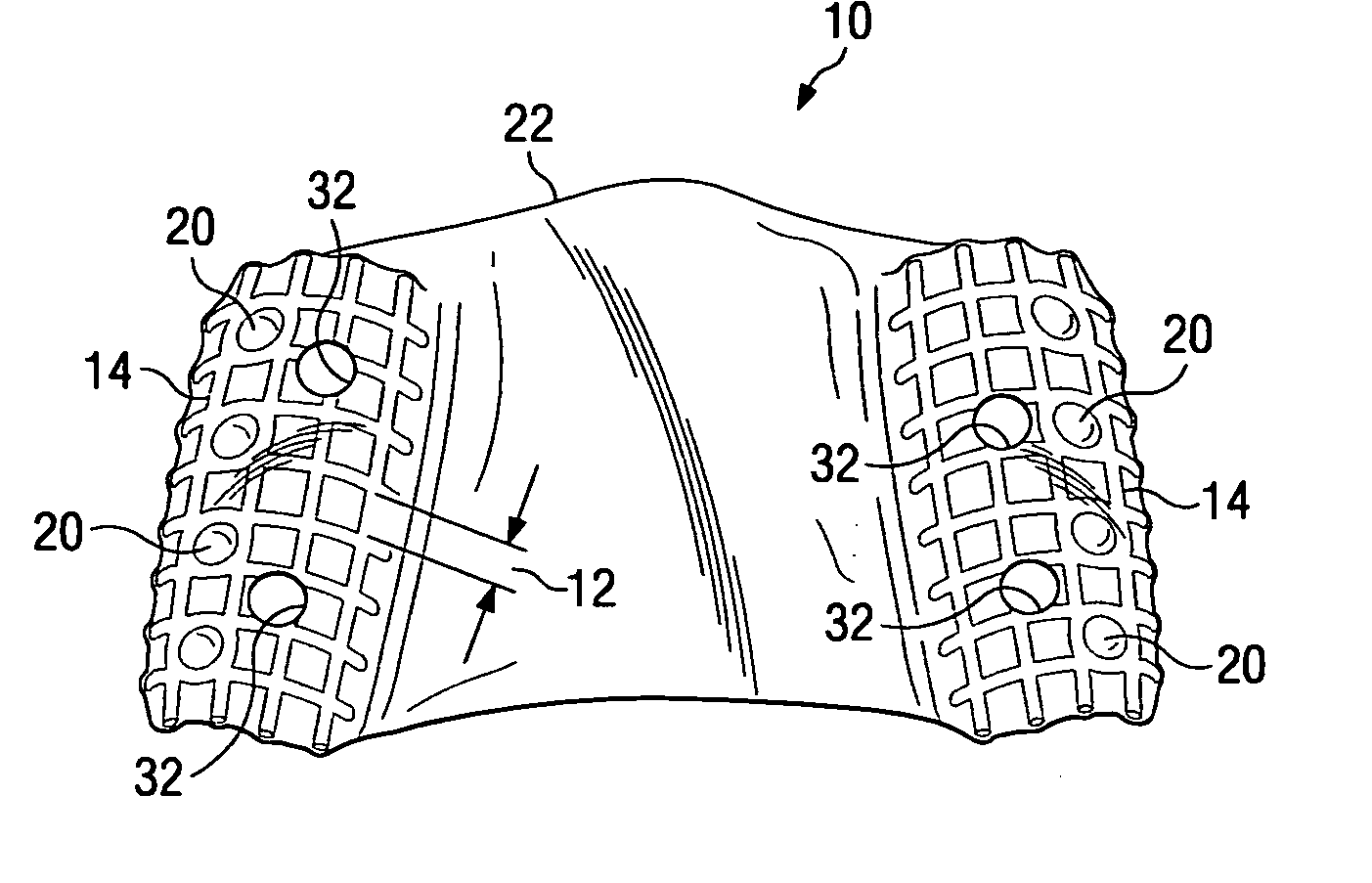
[0020] The implant placement locator of the present invention is seen in FIG. 1 and is generally referred to by reference number 10.

[0021] Implant placement locator 10 is comprised of visible or visibly opaque moldable grid 14 having grid spacing 12, radiopaque markers 20 located at indexed intervals on moldable grid 14, and plastic sheeting 22 which encases moldable grid 14 and radiopaque markers 20.

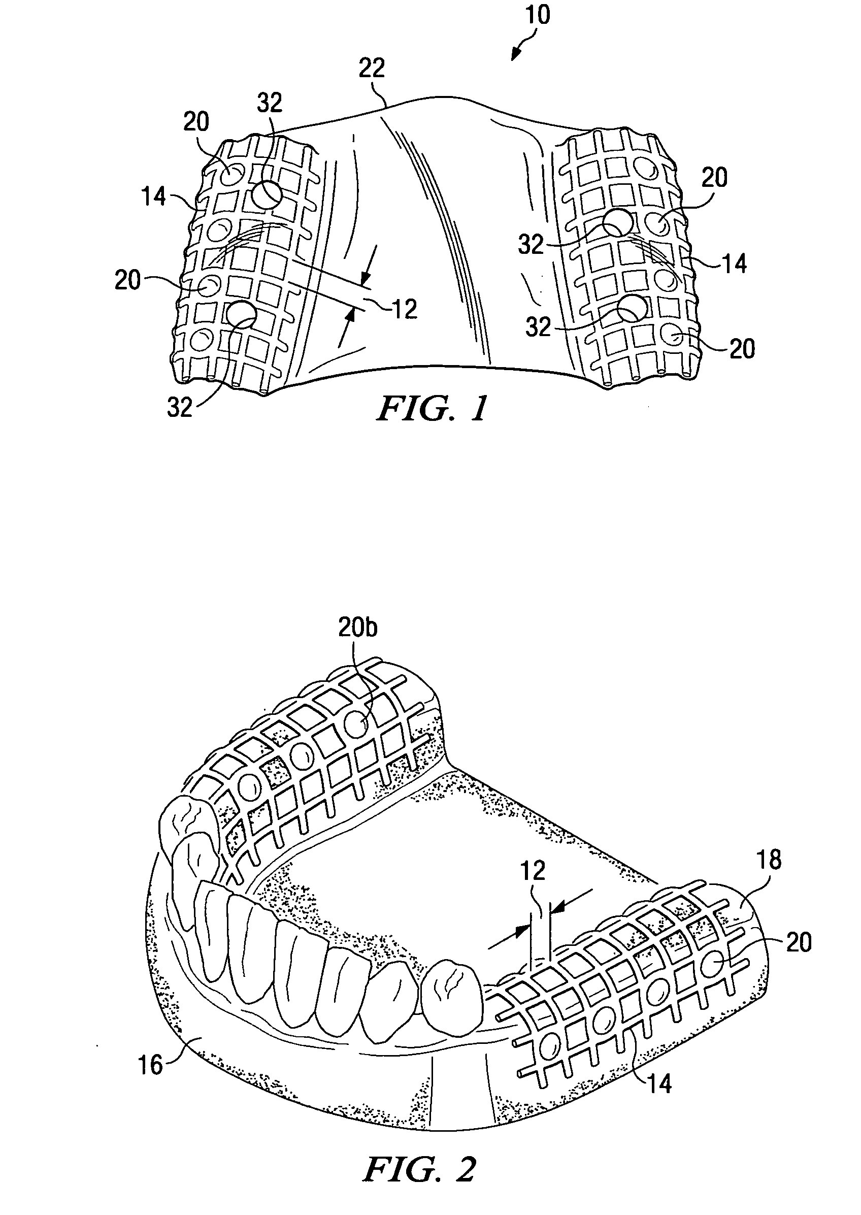
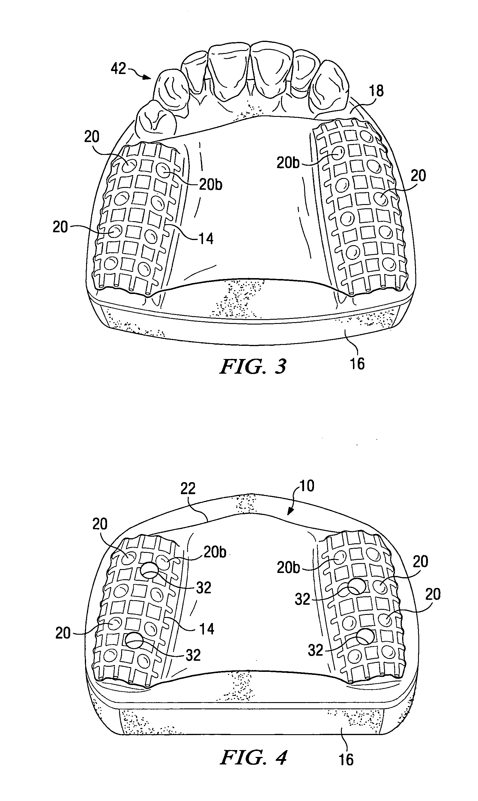
[0022] Implant placement locator 10 is designed to be placed in the patient's mouth in a variety of configurations, as required for a particular dental implant procedure. Referring to FIG. 2, in one embodiment, moldable grid 14 of implant placement locator 10 can cover the right or left dental ridge 18 on the upper or lower jaw, also respectively described as the ...


PUM


Abstract

The present invention provides a device and method for facilitating the placement of dental implants by use of an implant placement locator and a sequentially sized drill orientation tube series. The implant placement locator disclosed herein comprises a visible radiolucent moldable grid, a set of radiopaque markers located at known intervals within the moldable grid, and a plastic sheeting encasing the visible radiolucent moldable grid and the radiopaque markers. The method of the present invention comprises obtaining a radiograph of a patient's mouth with the implant placement locator overlaying the patient's dental ridge and then transferring reference points as indicated by the location of the radiopaque markers relative to existing teeth and other oral structures to a dental stone model. In a preferred embodiment, drill bits are directed in the desired trajectory into the patient's available lower or upper jaw bone by use of drill orientation tubes in combination with the implant placement locator. A sequentially sized set of spacers is provided having sequentially sized inside diameters to direct varying diameter drills. Drill guide parallelism is thus provided by the invention.

Description

FIELD OF THE INVENTION [0001] The present embodiments relate to a device and method for indexing radiographic locations of dental structures to markers to facilitate implant surgery and placement of dental implants. The present embodiments further relate to a device and method for directing a drill bit to a specific drill site and angle for the placement of dental implants. BACKGROUND OF THE INVENTION [0002] Devices and methods for fabricating dental templates, utilizing radiopaque substances in connection with dental stents and manufacturing dental implant structures are disclosed in the following: U.S. Application No. 2004 / 0166462 A1 to Phan, U.S. Pat. No. 5,897,696 to Giordano, U.S. Pat. No. 5,415,546 to Cox, and U.S. Pat. No. 6,382,975 B1 to Poirier. Difficulties encountered in the placement of dental implants include maintaining the accuracy of placements and efficiently utilizing evidence of bone available for surgical drilling. [0003] Surgical drills are typically used during...

Claims


Application Information

Patent Timeline
IPC IPC(8): A61C3/00
CPCA61C8/0089A61C1/084
Inventor SHELTON, ROBERT
Owner SHELTON ROBERT
Why Eureka
Try Eureka