
Method of making an indirect bonding tray for orthodontic treatment

a technology of indirect bonding and orthodontic treatment, which is applied in the field of indirect bonding tray, can solve the problems of difficulty in seeing the precise position of the bracket relative to the tooth surface, difficulty in accessing the surface of malposed teeth, and intruding teeth in the final position of the orthodontist using a straight-wire techniqu

Active Publication Date: 2006-11-16
3M INNOVATIVE PROPERTIES CO
View PDF3 Cites 76 Cited by
  • Summary
  • Abstract
  • Description
  • Claims
  • Application Information

AI Technical Summary

Benefits of technology

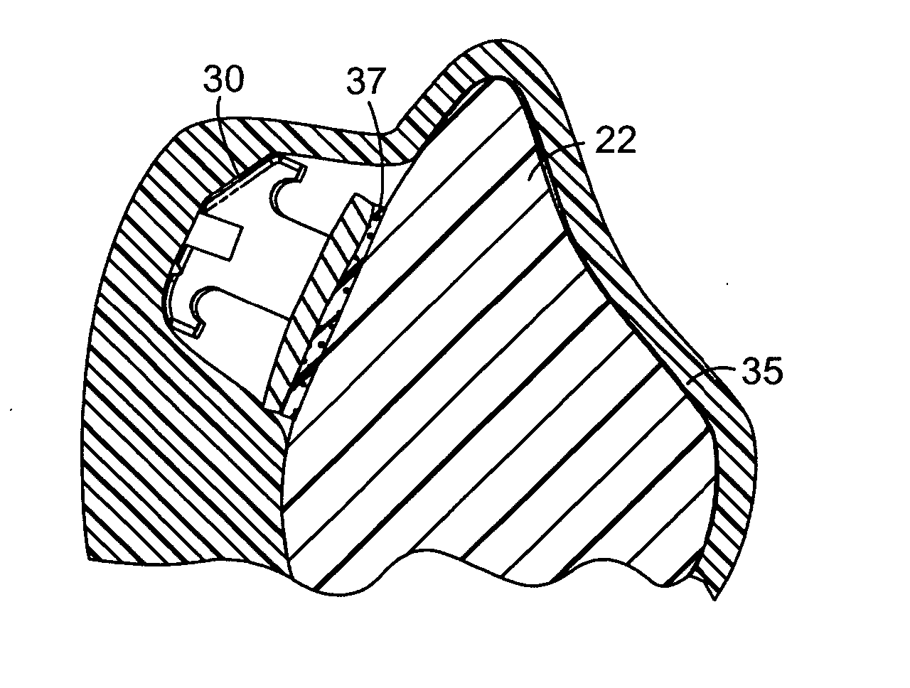
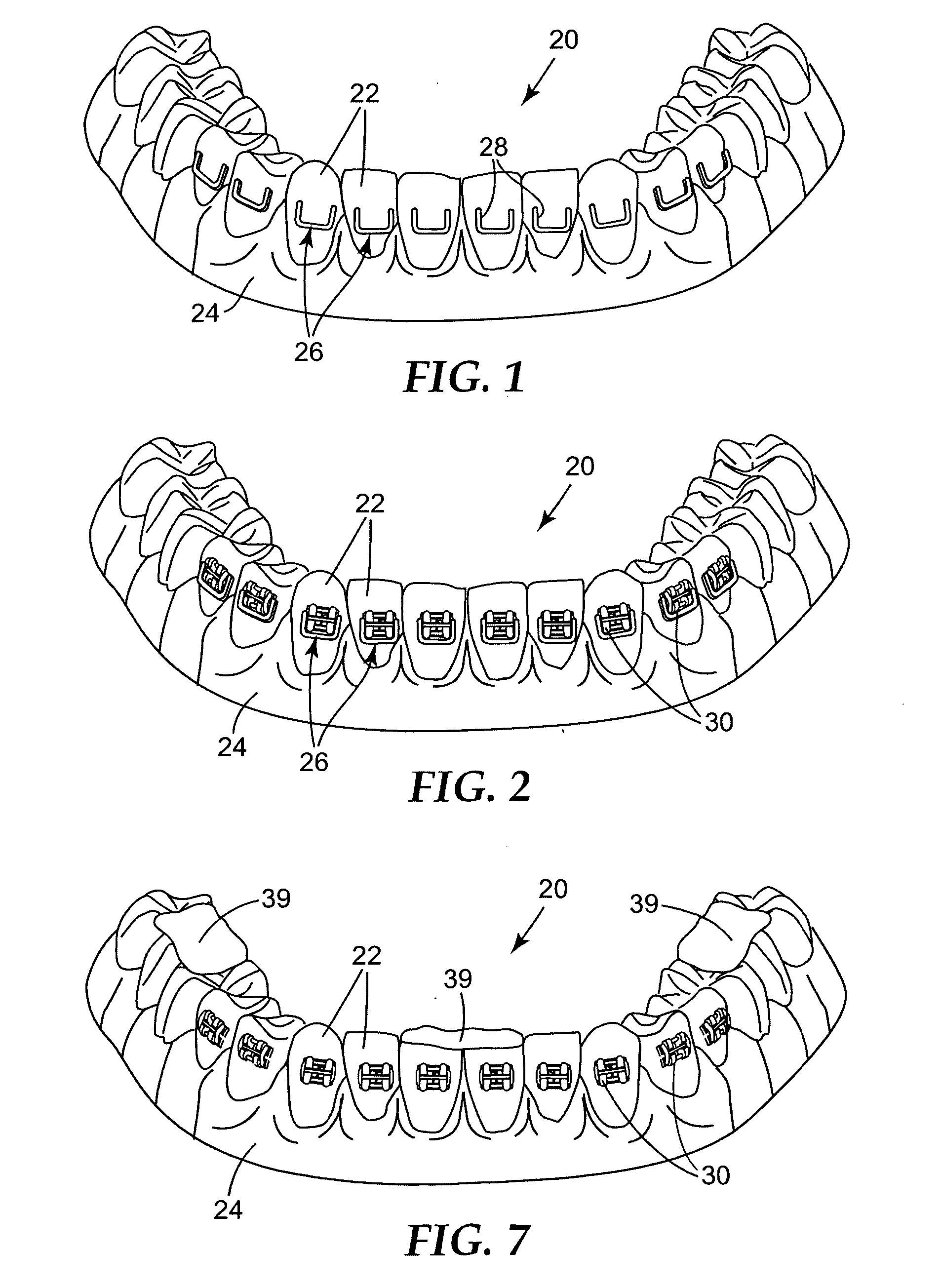
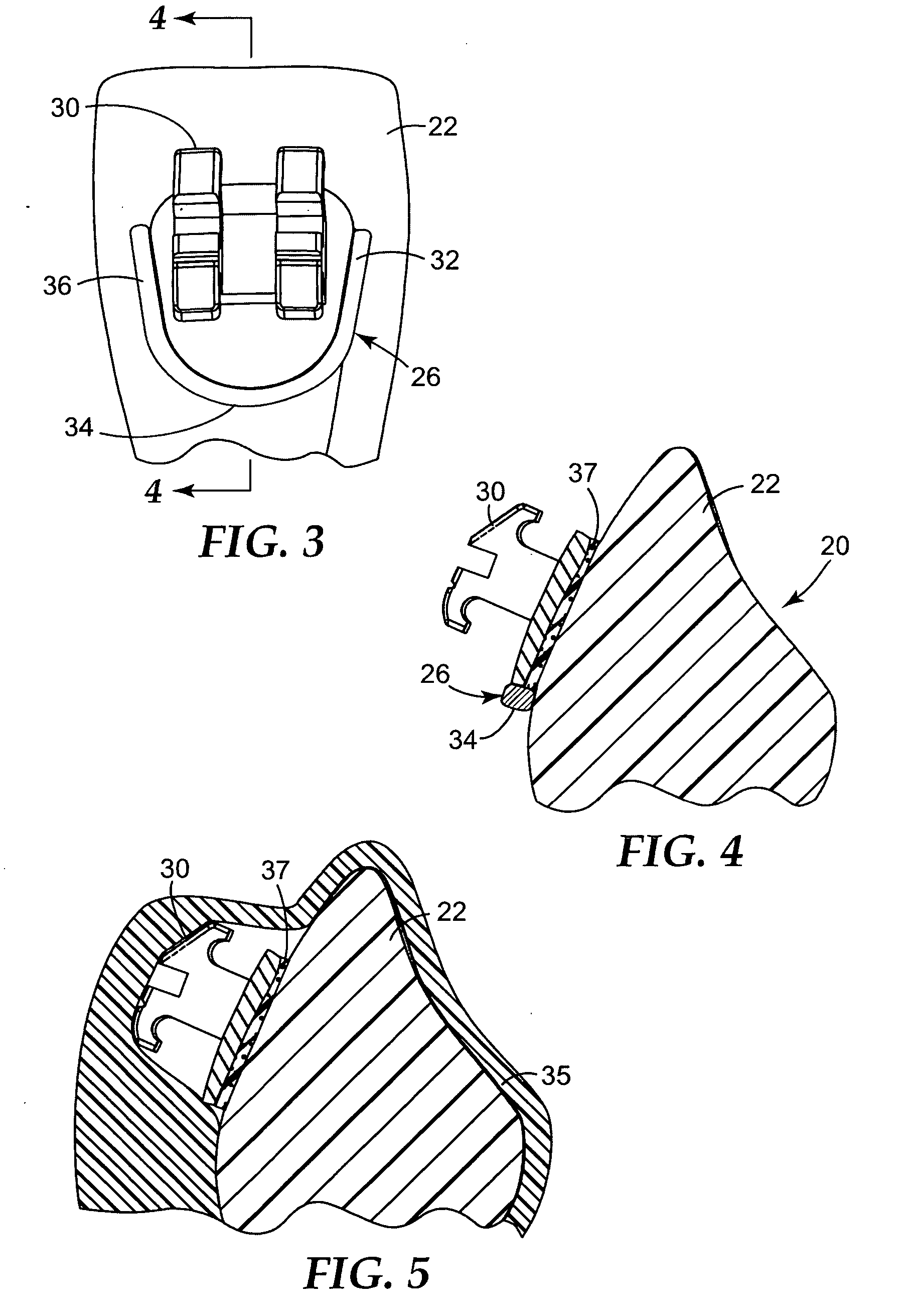
The present invention provides improved methods and assemblies for making an indirect bonding tray for orthodontic treatment. The invention involves making a replica of a patient's dentition and providing guides on the replica tooth structure that correspond to the intended location of orthodontic appliances on the patient's tooth structure. An orthodontic appliance is then placed on the replica tooth structure next to the guide, and a tray is formed over the replica including the orthodontic appliance. The invention helps to position the orthodontic appliance in its precise, intended location on the replica tooth, avoiding the use of manual positioning techniques or an automated robotic arm. The invention simplifies the process of making an indirect bonding tray for orthodontic treatment.

Problems solved by technology

Consequently, if a bracket is attached to the tooth at a location that is too close to the occlusal or outer tip of the tooth, the orthodontist using a straight-wire technique will likely find that the tooth in its final position is unduly intruded.
For example, access to surfaces of malposed teeth may be difficult.
In some instances, and particularly in connection with posterior teeth, the practitioner may have difficulty seeing the precise position of the bracket relative to the tooth surface.
Additionally, the appliance may be unintentionally dislodged from its intended location during the time that the excess adhesive is being removed adjacent the base of the appliance.
Another problem associated with the direct bonding technique described above concerns the significant length of time needed to carry out the procedure of bonding each appliance to each individual tooth.
At the same time, however, the patient may experience discomfort during the procedure and have difficulty in remaining relatively motionless, especially if the patient is an adolescent.
However, the use of a robotic arm to place appliances on replica teeth presents difficulties in the manufacturing process of making the trays.
Consequently, it would be a somewhat expensive task to set up an automated system for feeding the appliances to the robotic arm due to the large number of available appliances that may be needed for any particular patient.
Moreover, it may be difficult to construct a set of universal jaws for the robotic arm in order to pick up each appliance, as the external shape of the various appliances may greatly differ.

Method used


Image

  • Method of making an indirect bonding tray for orthodontic treatment
  • Method of making an indirect bonding tray for orthodontic treatment
  • Method of making an indirect bonding tray for orthodontic treatment

Examples


Embodiment Construction

[0047] A replica of a portion of a dental arch of an orthodontic patient is designated broadly by the numeral 20 in FIG. 1. For exemplary purposes, the replica 20 represents the patient's lower dental arch. However, a replica of a patient's upper dental arch may also be provided as an addition to or as an alternative to the lower dental arch replica 20 as shown. As a further option, the replica 20 may represent only a portion of the dental arch, such as a quadrant of an arch or only one or two teeth of a dental arch.

[0048] In the example illustrated, the replica 20 includes a number of replica teeth 22, each corresponding to one of the teeth of the patient's lower dental arch. In addition, the replica 20 includes replica gingival tissue 24. However, the replica gingival tissue 24 is optional, and may be provided only to an extent needed to securely hold the replica teeth 22 together.

[0049] A number of placement guides 26 extend over the dentition replica 20. In the example illustr...


PUM


Abstract

An indirect bonding tray for use in applying and bonding orthodontic appliances to a patient's teeth is made by providing a replica of the patient's dentition including replicas of the patient's teeth. A guide is provided on each replica tooth in a location corresponding to the ultimate intended location of the orthodontic appliance on the patient's teeth. Each guide has a receptacle for receiving an orthodontic appliance, and serves to ensure that the respective orthodontic appliance is placed in its proper, intended position on the replica tooth. A tray is then formed over the replica teeth and the appliances for subsequent use in bonding the appliances to the patient's teeth.

Description

BACKGROUND OF THE INVENTION [0001] 1. Field of the Invention [0002] This invention relates to an indirect bonding tray that is used for placing orthodontic appliances on the surfaces of a patient's teeth. More particularly, the present invention is directed toward a method and an assembly for making an indirect bonding tray. [0003] 2. Description of the Related Art [0004] Orthodontic treatment involves movement of malpositioned teeth to desired locations in the oral cavity. Orthodontic treatment can improve the patient's facial appearance, especially in instances where the teeth are noticeably crooked or where the jaws are out of alignment with each other. Orthodontic treatment can also enhance the function of the teeth by providing better occlusion during mastication. [0005] One common type of orthodontic treatment involves the use of tiny, slotted appliances known as brackets. The brackets are fixed to the patient's teeth and an archwire is placed in the slot of each bracket. The ...

Claims


Application Information

Patent Timeline
Patent Type & Authority Applications(United States)
IPC IPC(8): A61C3/00A61C11/00
CPCA61C7/146B33Y80/00B33Y50/00
Inventor CINADER, DAVID K. JR.CLEARY, JAMES D.
Owner 3M INNOVATIVE PROPERTIES CO
Learn More