Method and apparatus for minimizing error in dynamic and steady-state processes for prediction, control, and optimization

a dynamic and steady-state process and optimization technology, applied in the field of model techniques, can solve problems such as insufficient non-linear information in the dynamic data set, inability to account for perturbations, and inability to adequately model the gain of the system for an existing set of steady-state operating conditions

Inactive Publication Date: 2006-11-16
ROCKWELL AUTOMATION TECH
View PDF78 Cites 26 Cited by
  • Summary
  • Abstract
  • Description
  • Claims
  • Application Information

AI Technical Summary

Benefits of technology

[0007] The present invention disclosed and claimed herein comprises a method and apparatus for controlling the operation of a plant by predicting a change in the dynamic input values to the plant to effect a change in the output from a current. output value at a first time to a desired output value, at a second time. The controller includes a dynamic predictive model fore receiving the current input value and the desired output value and predicting a plurality of input values at different time positions between the first t

Problems solved by technology

These measurements do not account for the perturbations that exist when changing from one steady-state condition to another steady-state condition.
Unfortunately, almost always the dynamic gain k does not equal the steady-state gain K, since the steady-state gain is modeled on a much larger set of data, whereas the dynamic gain is defined around a set of operating conditions wherein an existing set of operating conditions are mildly perturbed.
This results in a shortage of sufficient non-linear information in the dynamic data set in which non-linear information is contained within the static

Method used


Image

  • Method and apparatus for minimizing error in dynamic and steady-state processes for prediction, control, and optimization
  • Method and apparatus for minimizing error in dynamic and steady-state processes for prediction, control, and optimization
  • Method and apparatus for minimizing error in dynamic and steady-state processes for prediction, control, and optimization

Examples


Embodiment Construction

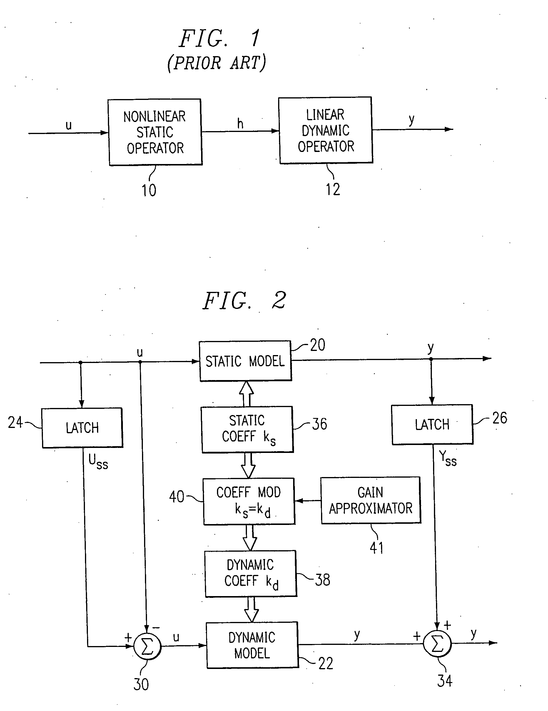
[0039] Referring now to FIG. 1, there is illustrated a diagrammatic view of a Hammerstein model of the prior art. This is comprised of a non-linear static operator model 10 and a linear dynamic model 12, both disposed in a series configuration. The operation of this model is described in H. T. Su, and T. J. McAvoy, “Integration of Multilayer Perceptron Networks and Linear Dynamic Models: A Hammerstein Modeling Approach” to appear in I &EC Fundamentals, paper dated Jul. 7, 1992, which reference is incorporated herein by reference. Hammerstein models in general have been utilized in modeling non-linear systems for some time. The structure of the Hammerstein model illustrated in FIG. 1 utilizes the non-linear static operator model 10 to transform the input U into intermediate variables H. The non-linear operator is usually represented by a finite polynomial expansion. However, this could utilize a neural network or any type of compatible modeling system. The linear dynamic operator mod...


PUM


Abstract

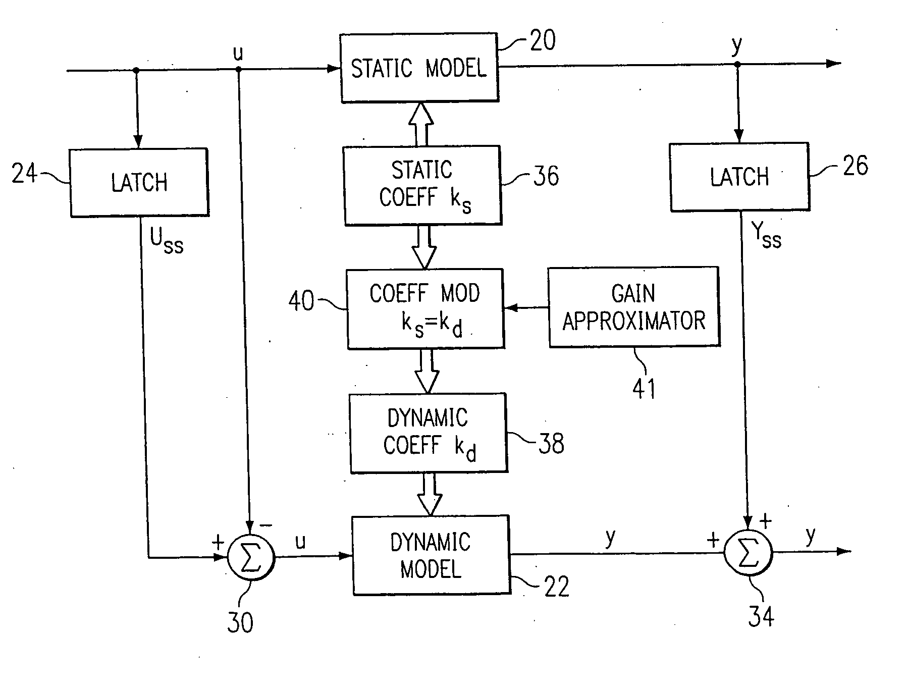
A method for providing independent static and dynamic models in a prediction, control and optimization environment utilizes an independent static model (20) and an independent dynamic model (22). The static model (20) is a rigorous predictive model that is trained over a wide range of data, whereas the dynamic model (22) is trained over a narrow range of data. The gain K of the static model (20) is utilized to scale the gain k of the dynamic model (22). The forced dynamic portion of the model (22) referred to as the bi variables are scaled by the ratio of the gains K and k. The bi have a direct effect on the gain of a dynamic model (22). This is facilitated by a coefficient modification block (40). Thereafter, the difference between the new value input to the static model (20) and the prior steady-state value is utilized as an input to the dynamic model (22). The predicted dynamic output is then summed with the previous steady-state value to provide a predicted value Y. Additionally, the path that is traversed between steady-state value changes.

Description

CROSS-REFERENCE TO RELATED APPLICATIONS [0001] This application is a Continuation in Part of U.S. patent application Ser. No. 10 / 847,211, filed May 17, 2004, entitled “Dynamic Controller for Controlling a System”, which is a Continuation of U.S. patent appplication Ser. No. 10 / 302,923, filed Nov. 22, 2002, entitled “Method and Apparatus for Modeling Dynamic and Steady-State Processes for Prediction, Control, and Optimization”, which is a Continuation of U.S. Pat. No. 6,487,459, issued Nov. 26, 2002, entitled “Method and Apparatus for Modeling Dynamic and Steady-State Processes for Prediction, Control, and Optimization”, which is a Continuation of U.S. Pat. No. 5,933,345, issued Aug. 3, 1999, entitled “Method and Apparatus for Dynamic and Steady State Modeling Over a Desired Path Between Two End Points”.TECHNICAL FIELD OF THE INVENTION [0002] The present invention pertains in general to modeling techniques and, more particularly, to combining steady-state and dynamic models for the p...

Claims


Application Information

Patent Timeline
IPC IPC(8): G06F19/00
CPCG05B13/027G05B17/02G05B13/048G05B13/042G09B23/02
Inventor BOE, EUGENEPICHE, STEPHENMARTIN, GREGORY D.
Owner ROCKWELL AUTOMATION TECH
Why Eureka
Try Eureka