Trim paneling with miterless corner joints and related methods

Inactive Publication Date: 2006-11-23
QUESTECH CORP
View PDF13 Cites 4 Cited by
  • Summary
  • Abstract
  • Description
  • Claims
  • Application Information

AI Technical Summary

Benefits of technology

[0011] During installation, if necessary, the transition element can be cut between the coping profiles to effectively alter its length. Specifically, the distance between two coping profiles can be increased by making a cut between the coping profiles and positioning one or more span elements between the disjoined portions containing coping profiles. Conversely, the distance between two coping profiles can be reduced by making two parallel cuts in the transition element, removing a middle portion, and joining the portions c

Problems solved by technology

Both do-it-yourselfers and professional installers often face difficulties when installing paneling elements around edges, boundaries, corners and joints, because the elements preferably have to be configured to fit snugly in place while forming corners.
A drawback to this approach is that an angled cut must be made in each of the paneling elements 102, 104 by the end user, and the probability of chipping, cracking, or breaking increases because the paneling material is thin near the intersection of the mitered planes 106,108 and the outside surface of the paneling element.
This approach, however, affords limited flexibility to the installer o

Method used


Image

  • Trim paneling with miterless corner joints and related methods
  • Trim paneling with miterless corner joints and related methods
  • Trim paneling with miterless corner joints and related methods

Examples


Embodiment Construction

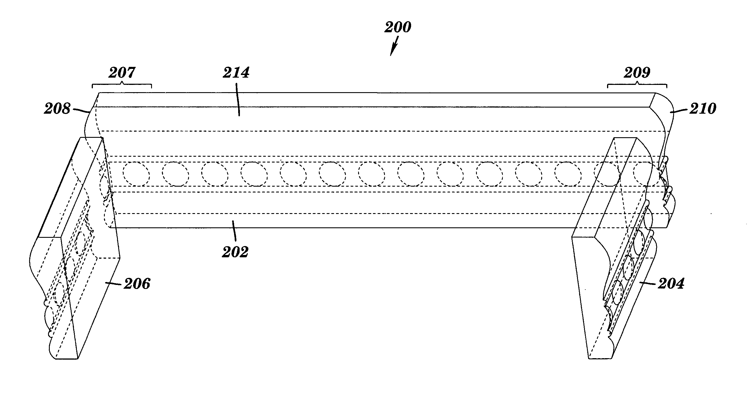
[0025] As mentioned above, various embodiments of the invention feature a paneling set that includes a transition element having two prefabricated coping profiles configured to mate with a span element at each end of the transition element, i.e. a single prefabricated transition element can be used to form two corners.

[0026] Referring to FIGS. 2A-2B, in one embodiment of the invention, a paneling set 200 includes a transition element 202 and span elements 204 and 206, whereby the transition element 202 is positioned to form a first corner with a first span element 204 and a second corner with a second span element 206. The elements of the paneling set have a rear face 214 and a front face 212. In various embodiments of the invention, the front faces 212 of both the span elements 204, 206 and the transition element 202 are designed to be substantially non-planar and decorative, whereas the rear faces are substantially planar, i.e. having a non-rectangular lateral cross-section.

[002...


PUM


Abstract

Disclosed herein is a paneling system including a first and a second span element each possessing a substantially non-rectangular lateral cross-section and at least one butt end having a surface substantially perpendicular to a longitudinal axis of the span element. The paneling system also includes a transition element having a first end defining a first coping profile, the first coping profile being mateable to the butt end of a first span element at substantially a right angle, and a second end defining a second coping profile, the second coping profile being mateable to the butt end of a second span element at substantially a right angle. Also disclosed is a method of installing a paneling system that includes arranging transition and span elements to mate and form miterless corners.

Description

FIELD OF THE INVENTION [0001] The present invention relates to paneling, and, more particularly, to a system and method of installing trim paneling with corner joints formed without miter cuts. BACKGROUND OF THE INVENTION [0002] Generally, paneling systems employ sequentially joined individual paneling elements, which may be used in conjunction with a surface, or are freestanding. For example, casing around a doorjamb includes a number of paneling elements that cover an underlying wall surface. As another example, decorative barriers, e.g. surrounding flowerbeds, typically consist of freestanding panel elements. Further, paneling systems may be employed in a functional manner or as decorative accents. [0003] Decorative panel elements having complex non-rectangular profiles and designed to cover a surface are often referred to as molding panels or simply moldings. Examples of molding panels include crown molding, base molding, chair molding, and cove molding. Moldings are often emplo...

Claims


Application Information

Patent Timeline
IPC IPC(8): E04C3/00
CPCE04F19/0436E04F19/0477E04F2019/0454E04F2019/0413E04F2019/0418E04F19/0495
Inventor QUESTEL, ROGER
Owner QUESTECH CORP
Why Eureka
Try Eureka