Linear guide apparatus
- Summary
- Abstract
- Description
- Claims
- Application Information
AI Technical Summary
Benefits of technology
Problems solved by technology
Method used
Image
Examples
embodiment 1
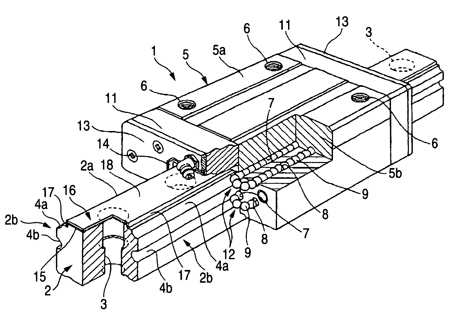
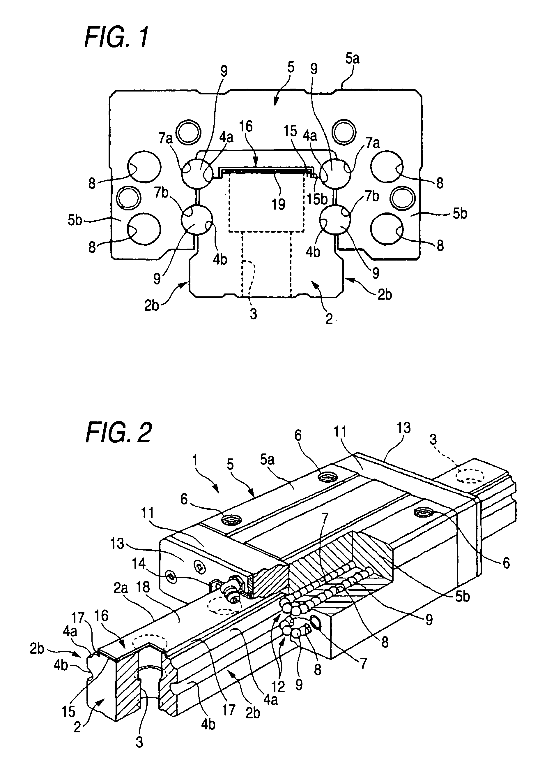
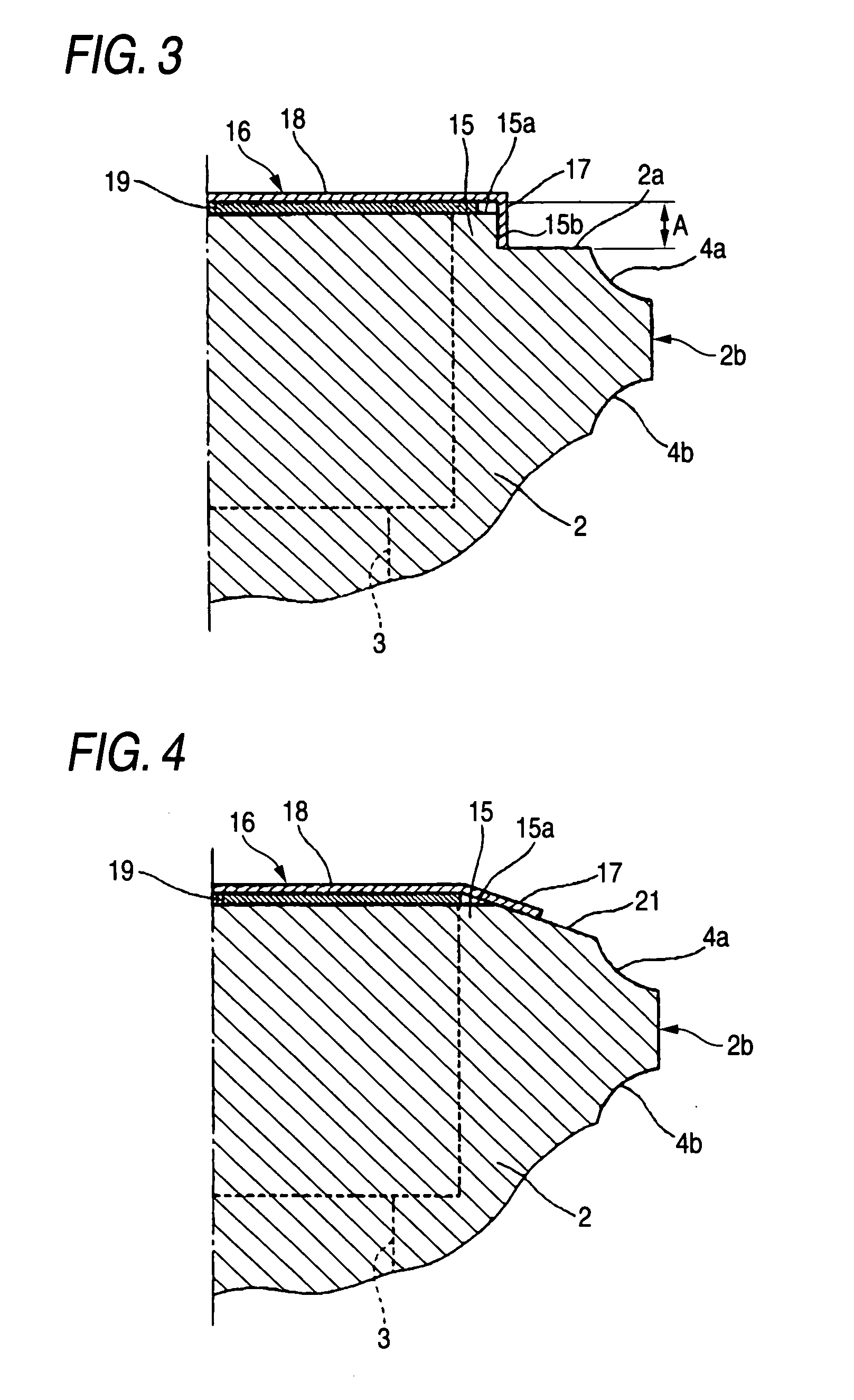
[0064]FIG. 1 is a front-elevational view showing a linear guide apparatus of Embodiment 1, FIG. 2 is a perspective view showing the linear guide apparatus of Embodiment 1, and FIG. 3 is an enlarged fragmentary view showing a rail and a rail cover of Embodiment 1.
[0065]FIG. 1 is the front-elevational view showing a condition in which end caps and side seals are removed.
[0066] In FIGS. 1 and 2, reference numeral 1 denotes the linear guide apparatus.
[0067] Reference numeral 2 denotes the rail of the linear guide apparatus 1, and the rail is a long bar-like member made of a steel material such as an alloy steel, and a plurality of rail mounting holes 3 (which are stepped bolt holes) are formed through the rail 2 in a direction of a height thereof, and are arranged at a predetermined pitch in a longitudinal direction thereof. The rail 2 is fastened to a base bed or the like of a machinery by bolts or the like, using these rail mounting holes 3, and is mounted thereon.
[0068] Rail trac...
embodiment 2
[0088]FIG. 4 is an enlarged fragmentary view showing a rail and a rail cover of Embodiment 2.
[0089] Those portions similar to those of the above Embodiment 1 will be designated by identical reference numerals, respectively, and explanation thereof will be omitted.
[0090] In FIG. 4, reference numeral 21 denotes an inclination surface serving as a slanting surface, and a protrusion 15 is formed on a rail upper surface 2a, and has a width larger than a bore of each rail mounting hole 3, and the inclination surfaces are defined respectively by flat surfaces which are formed respectively at opposite side corner portions of the protrusion 15 extending in a longitudinal direction of a protrusion upper surface 15a, and are slanting from the protrusion upper surface 15 toward a lower surface of the rail 2 in such a manner that the distance between the two flat surfaces in the widthwise direction is increasing. Therefore, the protrusion 15 of this embodiment has a trapezoidal cross-sectional...
embodiment 3
[0100]FIG. 6 is an enlarged fragmentary view showing a rail and a rail cover of Embodiment 3.
[0101] Those portions similar to those of the above Embodiment 1 will be designated by identical reference numerals, respectively, and explanation thereof will be omitted.
[0102] In FIG. 6, reference numeral 23 denotes a slanting upper surface which is a slanting rail upper surface formed between a lower edge of a fitting surface 15b of a protrusion 15 (formed in the same manner as described above for Embodiment 1) and an edge of a rail track groove 4a while the fitting surface 15b remains adjacent to a protrusion upper surface 15a of the protrusion 15.
[0103] Therefore, a rail cover 16 of this embodiment is similar to the rail cover 16 of Embodiment 1, but a length of each bent portion 17 thereof is made smaller by an amount equal to a height (height of a mountain) of a connected portion (of the slanting upper surface 23 and the fitting surface 15b) from a position corresponding to the rai...
PUM
 Abstract
Description
Claims
Application Information
 - R&D
- Intellectual Property
- Life Sciences
- Materials
- Tech Scout
- Unparalleled Data Quality
- Higher Quality Content
- 60% Fewer Hallucinations
Browse by: Latest US Patents, China's latest patents, Technical Efficacy Thesaurus, Application Domain, Technology Topic, Popular Technical Reports.
© 2025 PatSnap. All rights reserved.Legal|Privacy policy|Modern Slavery Act Transparency Statement|Sitemap|About US| Contact US: help@patsnap.com


