Brake pedal apparatus

a pedal apparatus and pedal technology, applied in the direction of mechanical control devices, instruments, manual control with single controlling member, etc., can solve the problems of not being able to change the lever ratio in time, and it is difficult to largely change the lever ratio halfway during the pedal stroke, so as to improve the degree of freedom in setting the lever ratio characteristic, improve the effect of braking operation feeling and easy chang

Inactive Publication Date: 2006-11-23
TOYODA IRON WORKS CO LTD
View PDF7 Cites 4 Cited by
  • Summary
  • Abstract
  • Description
  • Claims
  • Application Information

AI Technical Summary

Benefits of technology

[0014] Thus, the lever ratio characteristic in the first region and that in the second region can be set independently of each other, and the first and second regions can be suitably set, so that the lever ratio can be easily changed by a large amount at an arbitrary position during the pedal stroke, thereby improving a degree of freedom in setting of the lever ratio characteristic and providing a further excellent braking operation feeling.
[0015] In the second invention, the stopper is brought into contact with the third connecting pin, whereby one of the first and second links is unpivotably positioned. This arrangement can be constructed easier and cheaper than a case where a member such as an engaging pin is additionally provided to be brought into contact with the stopper.
[0016] In the third invention, one of the first and second links, which is to be brought into contact with the stopper so as to be unpivotably positioned, passes the third connecting pin and projects toward one of opposite sides of the third connecting pin that is remote from the first and second connecting pins, and the one of the first and second links has the engaging portion which is to be brought into contact with the stopper and which is provided on the outside of the third connecting pin. This arrangement increases a distance from the first or second connecting pin to the engaging portion, thereby amplifying a movement amount of the engaging portion. It is therefore possible to highly accurately control a pivot position of the first or second link in which the first or second link is brought into contact with the stopper, namely, a boundary between the first and second regions of the pedal stroke.

Problems solved by technology

However, in such a conventional brake pedal apparatus, since a characteristic of change of the lever ratio (lever ratio characteristic) is dependent on connected positions of the connecting link and contour of the cam, it is difficult to largely change the lever ratio halfway during the pedal stroke.
Thus, the change in the lever ratio is not necessarily satisfactory.

Method used


Image

  • Brake pedal apparatus
  • Brake pedal apparatus
  • Brake pedal apparatus

Examples


Embodiment Construction

[0036] There will be described in detail embodiments of the present invention, with reference to the drawings.

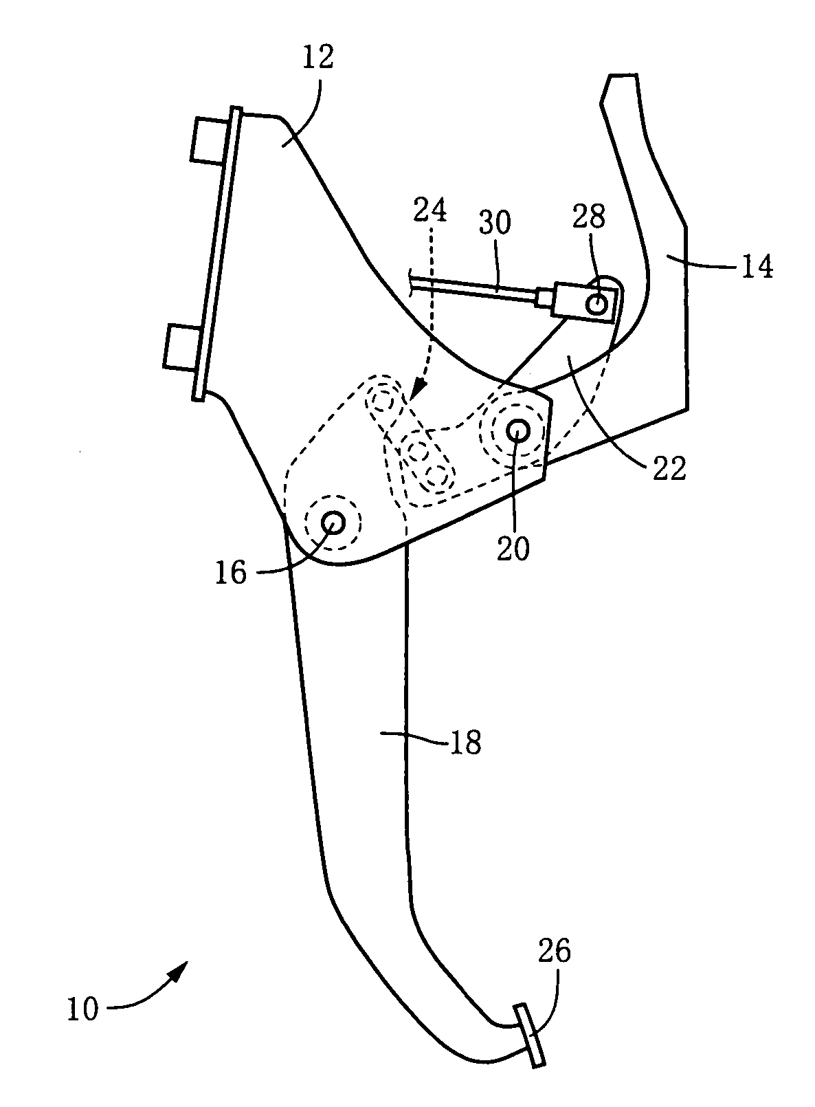
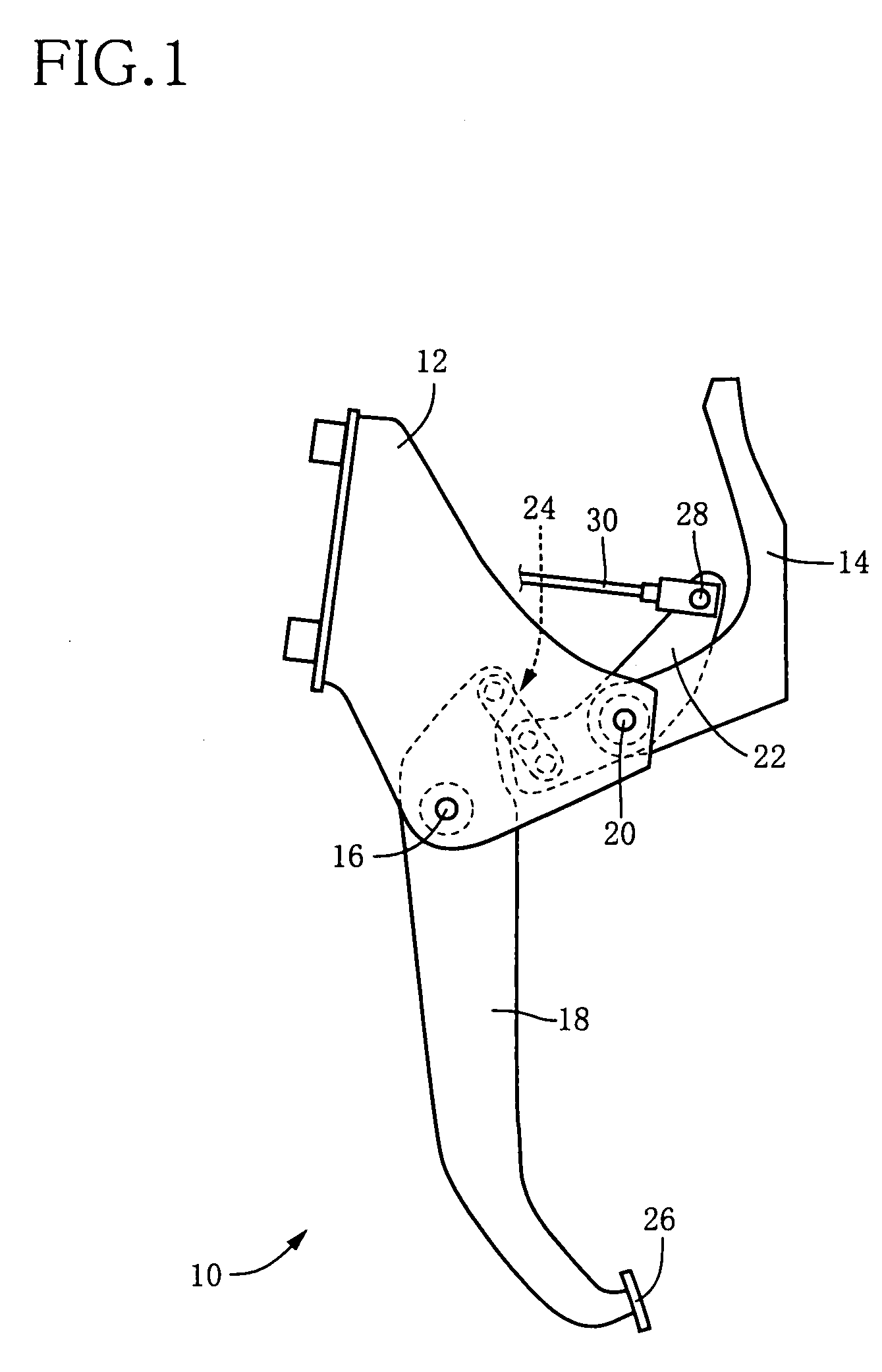
[0037]FIG. 1 is a front view schematically showing an embodiment of the invention in the form of a brake pedal apparatus 10 that is to be used for a service braking system of a vehicle. This brake pedal apparatus 10 is provided in brackets 12, 14 that are integrally fixed to a body of the vehicle. An operating pedal 18 is provided in the bracket 12, so as to be pivotable about an axis of a first support shaft 16 that is substantially horizontal. The brackets 12, 14 are connected through a second support shaft 20 on which a pivot member 22 is mounted to be pivotable about an axis of the second support shaft 20. A link mechanism 24 is provided to extend between the operating pedal 18 and the pivot member 22. The first and second support shafts 16, 20 are held in parallel to each other, and the axes of the first and second support shafts 16, 20 correspond to a first axis and a...


PUM


Abstract

The present invention is, in a brake pedal apparatus having: (a) an operating pedal which is disposed pivotably about a first axis; (b) a pivot member which is disposed pivotably about a second axis parallel to the first axis, and which is connected to the operating pedal via a connecting link so as to be mechanically pivoted about the second axis in response to a depressing operation effected on the operating pedal; and (c) an output member which is to be mechanically pressed or pulled as a result of pivot motion of the pivot member, in that: (d) the connecting link has a first link disposed on a member on a side of the operating pedal pivotably about a first connecting pin parallel to the first axis, and a second link disposed on a member on a side of the pivot member pivotably about a second connecting pin parallel to the first axis; (e) the first and second links are connected to each other via a third connecting pin pivotably relative to each other, and are integrally displaced with constant attitudes thereof that have the third connecting pin positioned on a straight line connecting the first and second connecting pins in a first region of a pedal stroke of the operating pedal; and (f) in a second region that is different from the first region, one of the first and second links is in contact with a stopper that is provided on the member on the side of the operating pedal or on the member on the side of the pivot member, so as to be unpivotably positioned, whereby the first and second links are pivoted relative to each other about the third connecting pin.

Description

[0001] This application is based on Japanese Patent Application No. 2005-144697, the content of which is incorporated hereinto by reference. BACKGROUND OF THE INVENTION [0002] 1. Field of the Invention [0003] The present invention relates in general to a brake pedal apparatus, and more particularly to such a brake pedal apparatus having a high degree of freedom in setting of a lever ratio characteristic. [0004] 2. Discussion of Prior Art [0005] There is known a brake pedal apparatus having (a) an operating pedal which is disposed pivotably about a first axis, (b) a pivot member which is disposed pivotably about a second axis parallel to the first axis, and which is connected to the operating pedal via a connecting link so as to be mechanically pivoted about the second axis in response to a depressing operation effected on the operating pedal; and (c) an output member which is to be mechanically pressed or pulled as a result of pivot motion of the pivot member. As an example of such ...

Claims


Application Information

Patent Timeline
Patent Type & Authority Applications(United States)
IPC IPC(8): G05G1/04B60T7/06G05G1/46G05G7/04
CPCB60T7/06Y10T74/20558G05G7/04G05G1/46
Inventor FUKASE, AKIHIKO
Owner TOYODA IRON WORKS CO LTD
Why Eureka
Try Eureka