Wheel cap and retainer assembly

a technology for retainers and wheels, applied in the direction of wheel protection, vehicle components, hubs, etc., can solve the problems of reducing the useful life of the wheel clad, affecting the appearance of the outer covering, and adding to the associated manufacturing costs of a vehicle line, so as to achieve easy and quick assembly, long operating life, and economic manufacturing

Inactive Publication Date: 2006-11-23
HAULER GREGORY R
View PDF31 Cites 11 Cited by
  • Summary
  • Abstract
  • Description
  • Claims
  • Application Information

AI Technical Summary

Benefits of technology

[0009] The present inventive wheel cover assembly provides a more durable and heat resistant wheel covering that may be operated / installed by even unskilled personnel, can be easily and quickly assembled, is economical to manufacture, capable of a long operating life while installed on the associated vehicle wheel, is dynamically adaptable to varying wheel configurations and is particularly well adapted for the proposed use.

Problems solved by technology

The heat received by the wheel may result in heat fatigue, thereby reducing the useful life of the wheel clad, as well as distortion and degradation to the aesthetic outer covering associated therewith.
This static sort of design for the vehicle wheels adds to the associated manufacturing costs across a line of vehicles, in that individual wheel coverings and associated clips and fasteners must be manufactured for each wheel of varying configuration.

Method used


Image

  • Wheel cap and retainer assembly
  • Wheel cap and retainer assembly
  • Wheel cap and retainer assembly

Examples


Embodiment Construction

[0023] For purposes of description herein, the terms “upper,”“lower,”“right,”“left,”“rear,”“front,”“vertical,”“horizontal,” and derivatives thereof shall relate to the invention as oriented in FIGS. 1 and 2. However, it is to be understood that the invention may assume various alternative orientations and step sequences, except where expressly specified to the contrary. It is also to be understood that the specific devices and processes illustrated in the attached drawings, and described in the following specification are exemplary embodiments of the inventive concepts defined in the appended claims. Hence, specific dimensions and other physical characteristics relating to the embodiments disclosed herein are not to be considered as limiting, unless the claims expressly state otherwise.

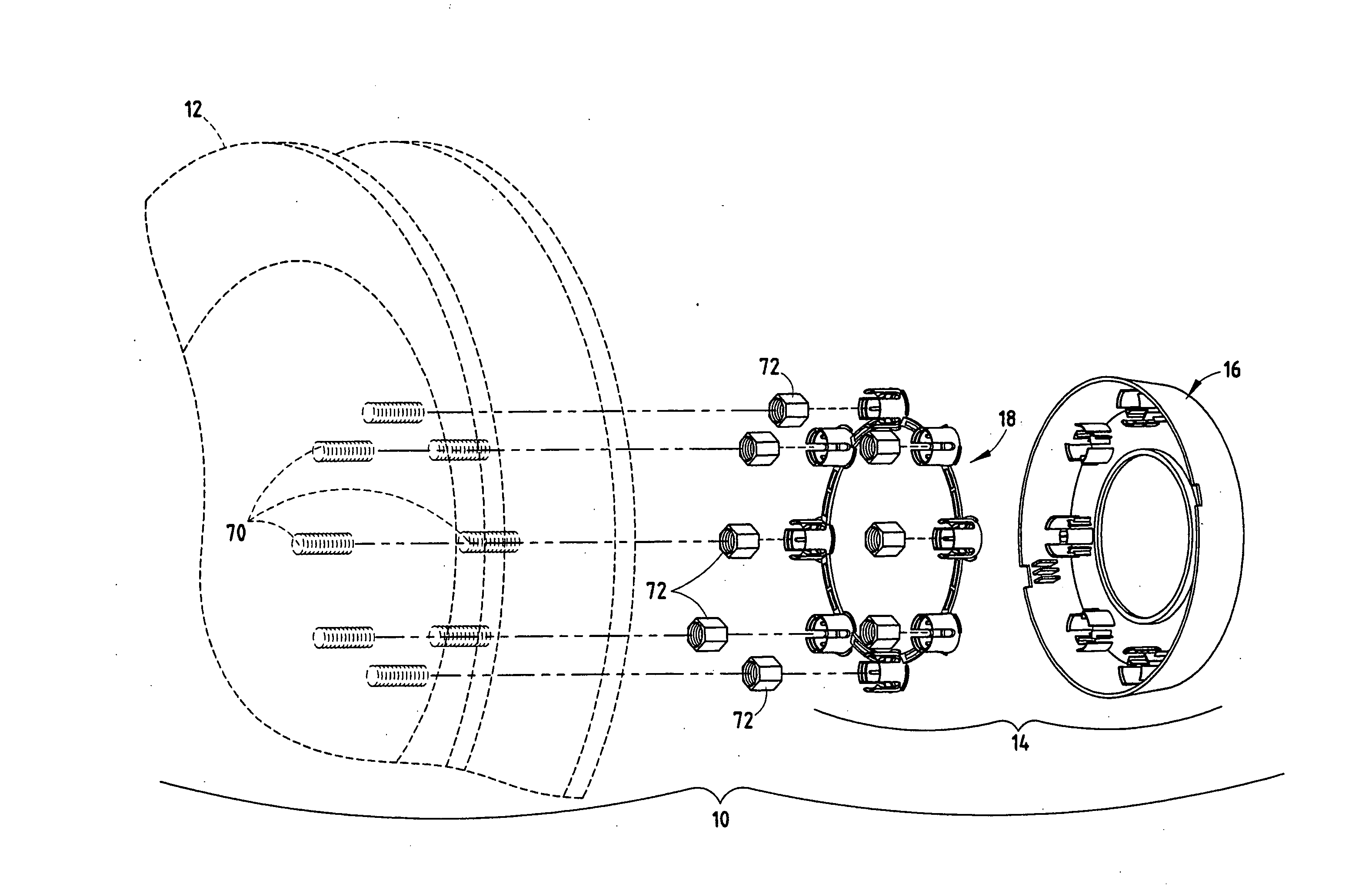
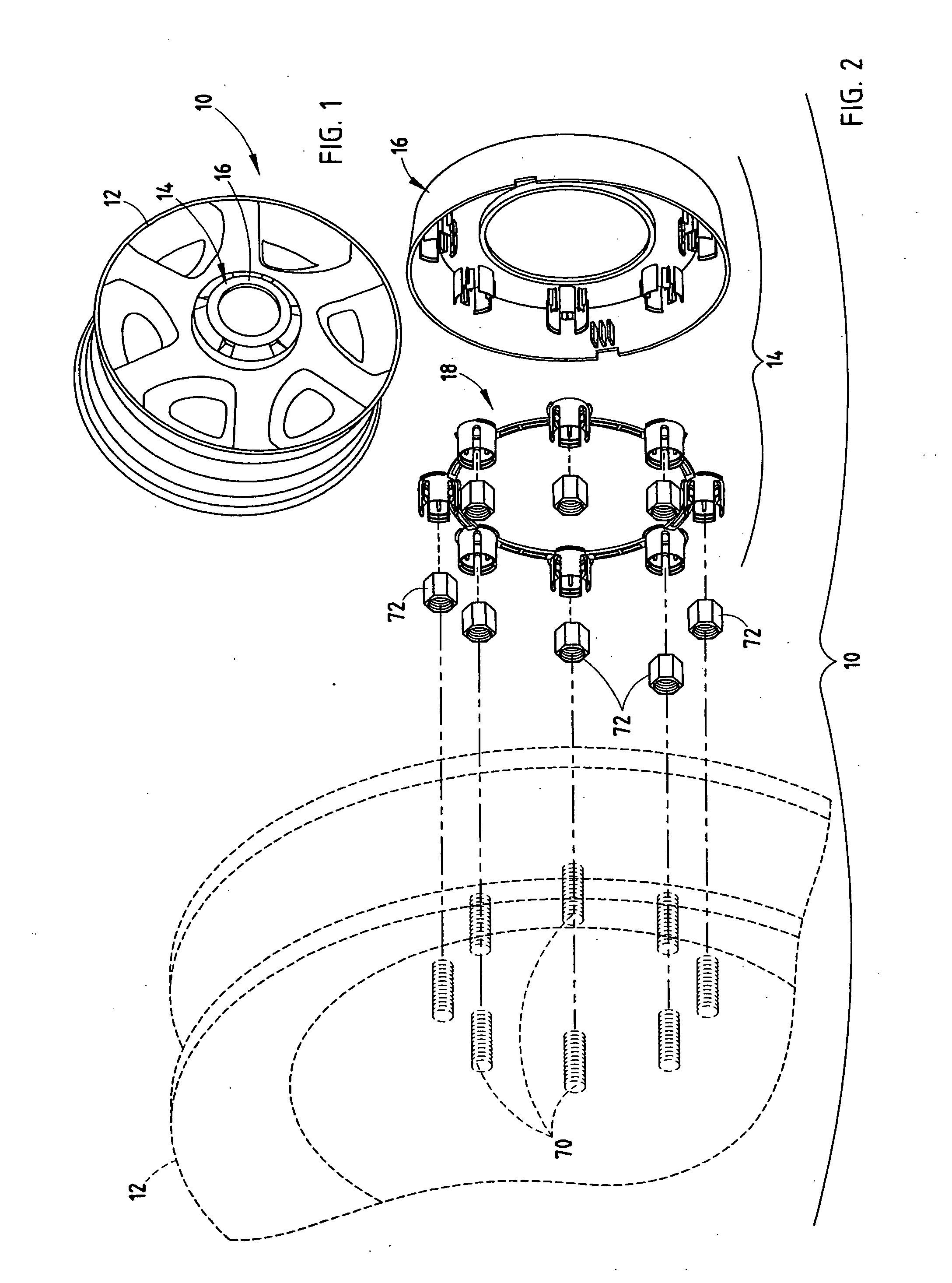
[0024] The reference numeral 10 (FIGS. 1 and 2) generally designates a wheel assembly that includes a vehicle wheel 12 and a wheel cover or clad assembly 14. The wheel cover assembly 14 includes a co...


PUM


Abstract

A wheel cover assembly comprises a wheel cover that includes a body portion having an outer surface and an inner surface opposed across the body portion from the outer surface, and at least one elongated tubularly-shaped extension having a proximal portion connected to the body portion, and a distal portion extending in a direction away from the inner surface of the body portion. The wheel cover assembly also includes at least one connector member having a proximal end snappably coupled with the distal end of the extension of the wheel cover, and a distal end adapted to releasably couple with a vehicle wheel.

Description

CROSS-REFERENCE TO RELATED APPLICATION [0001] This application is a continuation of U.S. patent application Ser. No. 10 / 757,311, filed Jan. 14, 2004, entitled WHEEL CAP AND RETAINER ASSEMBLY, the entire disclosure of which is incorporated herein by reference. BACKGROUND OF THE INVENTION [0002] The present invention relates to a wheel cover assembly, and in particular to a retainer assembly for releasably coupling a wheel cap or cover with a vehicle wheel. [0003] Ornamental outer coverings have been employed for providing a decorative surface to the exposed surface of a vehicle wheel for many years. These outer coverings offer design flexibility and various configurations that may be used to cover a single style wheel. In certain applications, the ornamental wheel covering is constructed of a polymeric material or plastic that is then coated with a metal plating. U.S. Pat. Nos. 5,564,791; 5,577,809; 5,597,213; 5,630,654; 5,636,906; 5,845,973; and 6,085,829, the disclosures of which a...

Claims


Application Information

Patent Timeline
Patent Type & Authority Applications(United States)
IPC IPC(8): B60B7/14B60B27/00B60B7/06
CPCB60B7/04B60B7/08B60B7/068
Inventor HAULER, GREGORY R.
Owner HAULER GREGORY R
Why Eureka
Try Eureka