Eureka AIR delivers breakthrough ideas for toughest innovation challenges, trusted by R&D personnel around the world.

Methods of constructing a betatron vacuum chamber and injector

a technology of betatron and vacuum chamber, which is applied in the direction of accelerators, electric discharge tubes, light sources, etc., can solve the problems of high level of liability associated with the handling and use of chemical sources, the host of logistical and political problems, and the general inability to meet the requirements of this borehole application

Active Publication Date: 2006-11-23
SCHLUMBERGER TECH CORP
View PDF7 Cites 18 Cited by
  • Summary
  • Abstract
  • Description
  • Claims
  • Application Information

AI Technical Summary

Benefits of technology

[0015] Further features and applications of the present invention will bec...

Problems solved by technology

However, the use of chemical sources creates a host of logistic and political issues.
For example, there is a high level of liability associated with the handling and use of chemical sources.
While electrostatic machines can provide the required energy level, they are generally not suited for this borehole application.
Likewise, linear RF machines can provide high intensity gamma-rays, however, their size and weight make them difficult to implement for borehole applications.
In addition, they tend to be cost prohibitive.
Accordingly, betatrons of this type are not reproducible in a manner consistent enough for mass production.
In addition, due to the many design problems (as described in part below), they have not been successfully implemented.
On a bare insulating surface such as glass, excessive wall charge may lead to the premature disintegration of the accelerating beam due to the electrostatic field generated by the trapped charges.
The application of this resistive coating to traditional glass blown vacuum chambers has proven quite challenging.
The proper positioning and alignment of the injector attached at the end of a long cantilever arm inside the traditional glass blown vacuum chamber are very challenging.
Accordingly, the mounting and alignment of the injector / target are two additional difficult design issues.
This presents additional challenges to the fabrication of the structure using traditional custom glass blown techniques.

Method used


Image

  • Methods of constructing a betatron vacuum chamber and injector
  • Methods of constructing a betatron vacuum chamber and injector
  • Methods of constructing a betatron vacuum chamber and injector

Examples


Embodiment Construction

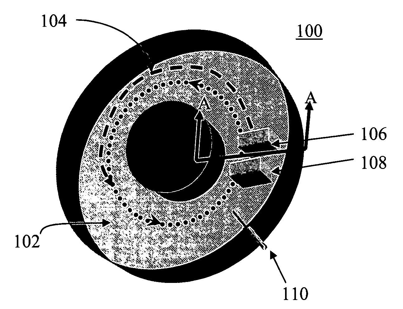
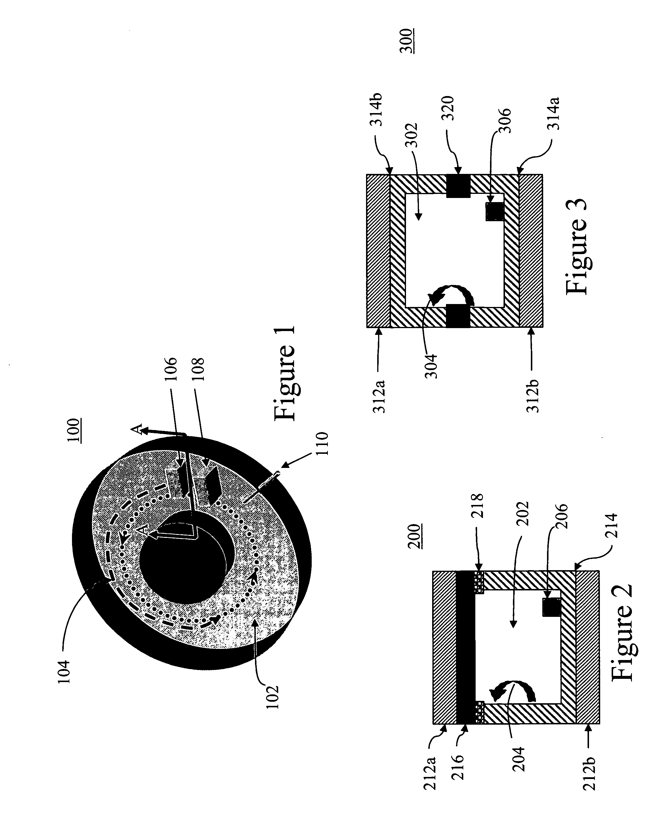
[0021] A betatron (gamma-ray source) is comprised of two main components: a modulator and a betatron structure. The modulator includes a power conditioning unit and a beam control unit. The betatron structure includes a magnet (shown in FIGS. 2 and 3), a vacuum chamber (shown in FIGS. 1, 2, and 3), and an injector (shown in FIG. 1). It is noted that the target may be integrated or combined with the injector structure.

[0022]FIG. 1 shows a general schematic of the betatron structure 100, having a donut-shaped vacuum chamber 102. An injector 106 and target 108 are positioned inside the accelerator chamber 102. It is noted that while injector 106 and target 108 are shown here as two different elements, one skilled in the art would recognize that the injector and target may be designed as a common element. Electrons injected into the chamber 102 by the injector 106 are trapped therein by the magnetic field created by magnets 212a, 212b (see FIG. 2). The electrons follow a generally circ...


PUM


Abstract

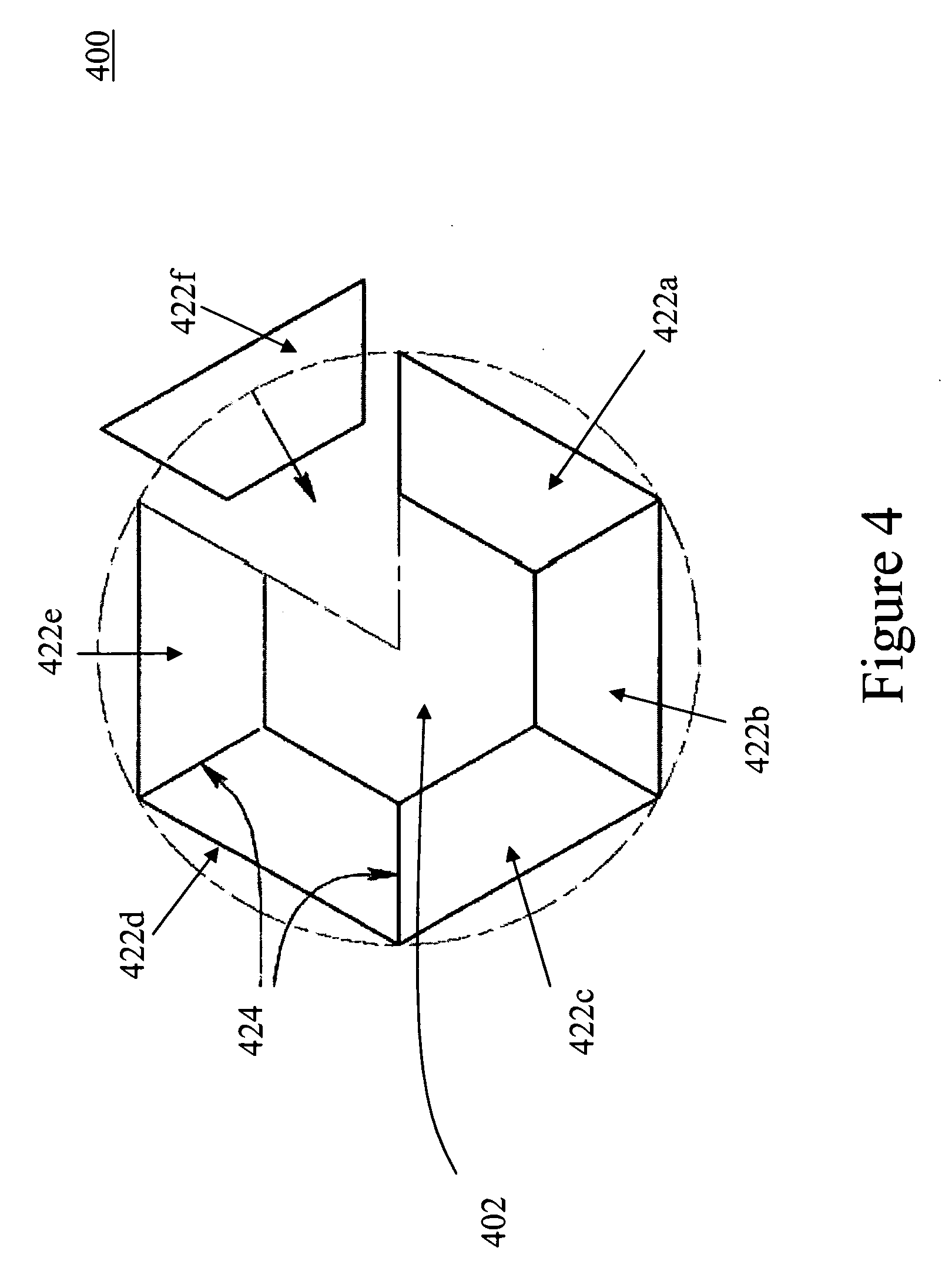
A betatron structure having a donut-shaped vacuum chamber, wherein the vacuum chamber is made up of two or more pieces bonded together; an injector positioned within the vacuum chamber; and two or more magnets positioned to the outside of the vacuum chamber. A method of manufacturing a betatron structure, including: (a) fabricating two or more pieces; (b) positioning an injector on one of the two or more pieces; and (c) bonding the two or more pieces such that when bonded, the substrates form a hollow donut-shaped chamber.

Description

CROSS-REFERENCE TO RELATED APPLICATIONS [0001] The present application claims the benefits of priority to U.S. Provisional Application Ser. No. 60 / 683,833, entitled “Methods of Constructing a Betatron Vacuum Chamber and Injector,” filed May 23, 2005, which are incorporated herein by reference in its entirety.FIELD OF THE INVENTION [0002] The present invention relates to a method and apparatus for a compact circular magnetic induction accelerator (betatron), and more particularly, to simpler and more efficient betatron vacuum chamber and injector design fabricated on the microscale. BACKGROUND OF THE INVENTION [0003] Nuclear tools have been used for several decades to determine the density of earth formations surrounding a borehole. Conventional density tools consist of a source of gamma-rays (or X-rays), at least one gamma-ray detector and shielding between the detector and the source, so that only scattered gamma-rays are detected. During density logging, gamma-rays from the tool s...

Claims


Application Information

Patent Timeline
IPC IPC(8): H05H7/00
CPCH05H11/00H05H7/14
Inventor CHEN, FELIX K.WONG, JOYCECORRIS, GARY W.BALKUNAS, STEPHENZHOU, ZILUHAUG, JAMES G.
Owner SCHLUMBERGER TECH CORP
Why Eureka
Eureka Blog
Learn More