Magnetic rotation angle sensor

Active Publication Date: 2006-11-23
DENSO CORP
View PDF6 Cites 14 Cited by
  • Summary
  • Abstract
  • Description
  • Claims
  • Application Information

AI Technical Summary

Benefits of technology

[0008] The present invention is achieved in view of the above-described issues, and has an object to provide a small magnetic rotation angle sensor in which a magnet and a magnetic flux density dete

Problems solved by technology

This construction increases the number of parts, and raises a manufacturing cost.
The magnetic flux generated by the magnet flows much toward the yoke than toward the magnetic detection device in this magnetic circuit construction, to cause an issue to decrease an output level of the magnetic detection device.
The magnetic flux quantity generated by the magnet can be increased by forming t

Method used


Image

  • Magnetic rotation angle sensor
  • Magnetic rotation angle sensor
  • Magnetic rotation angle sensor

Examples


first embodiment

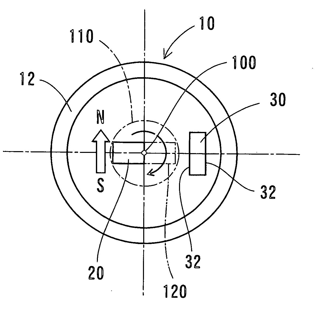
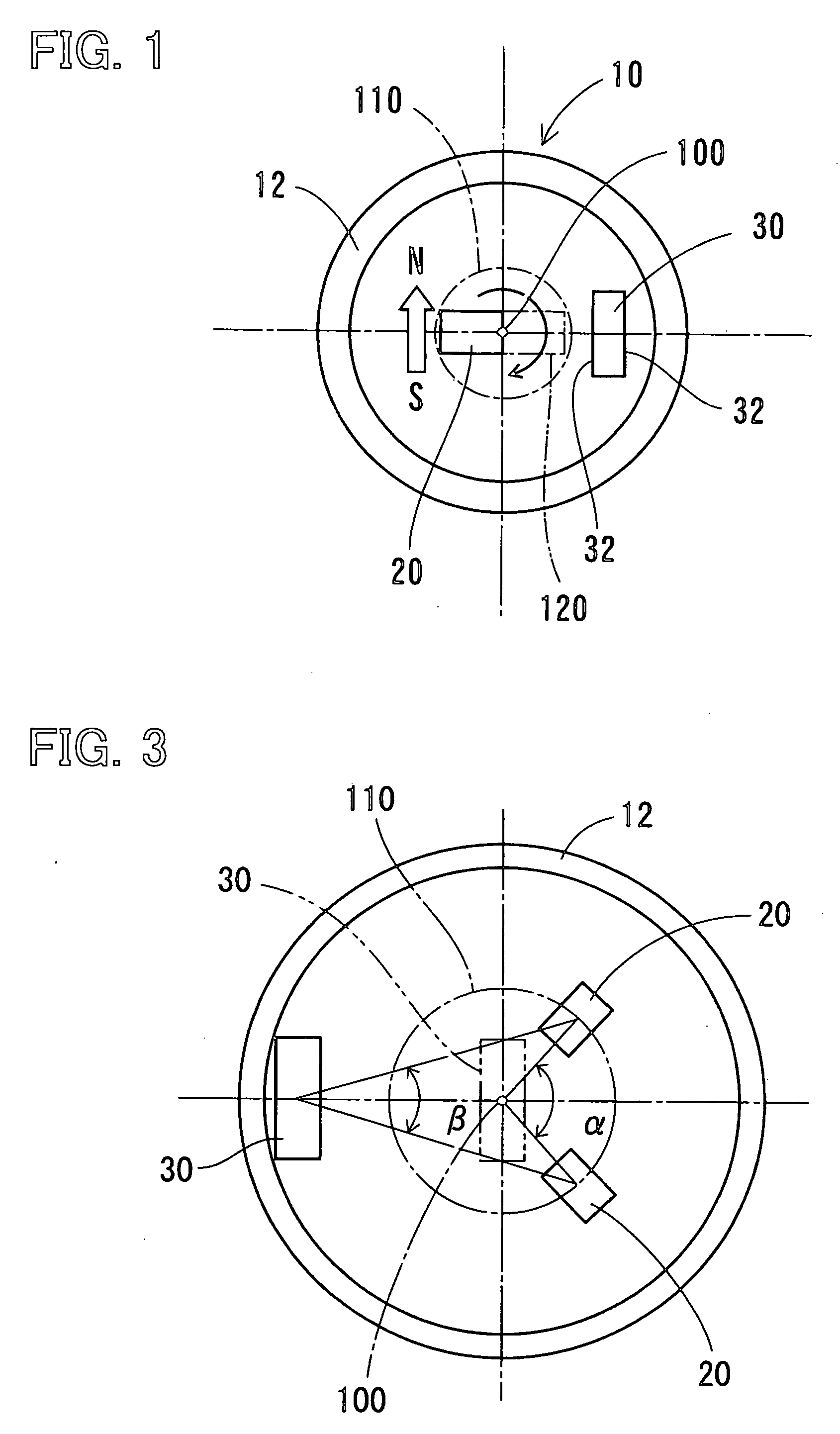
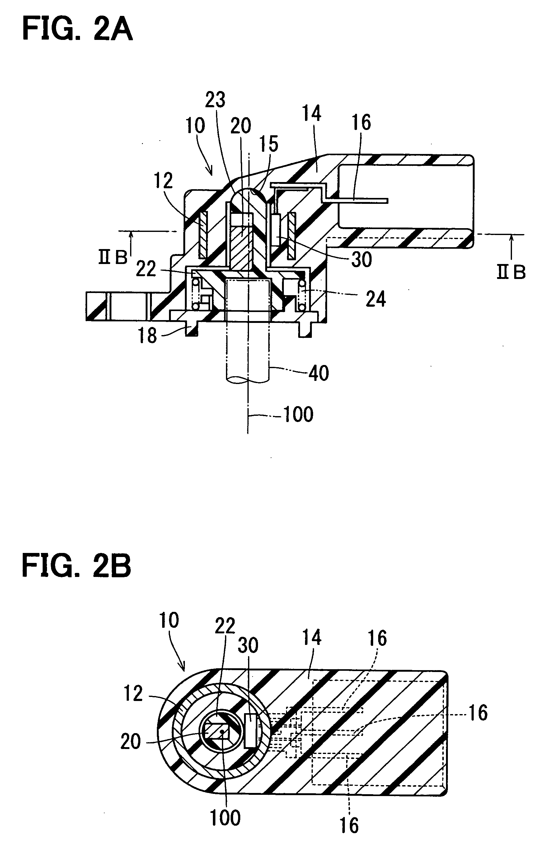
[0025]FIG. 1 depicts a magnetic rotation angle sensor 10 according to a first embodiment of the present invention. The magnetic rotation angle sensor 10 is a device for detecting a rotation angle of a detection target such as a throttle valve element. The magnetic rotation angle sensor 10 has a yoke 12, a magnet 20 and a Hall IC 30, which is an example of the magnetic flux density detection device according to the present invention. A Hall effect device may substitute for the Hall IC 30. The yoke 12 covers outer circumferences of the magnet 20 and the Hall IC 30.

[0026] The yoke 12 is formed from magnetic material into a cylindrical shape. The magnet 20 is a permanent magnet that rotates integrally with the detection target and is installed on a radially shifted position from a rotation center 100 of the detection target. The magnet 20 is magnetized along a turning circle of the detection target. The Hall IC 30 is installed on a radially shifted position from the rotational center 1...

second embodiment

[0052]FIG. 11 depicts an electromagnetic rotation angle sensor 50 according to a second embodiment of the present invention. In FIG. 11, components, to which the same referential numerals are assigned as in the first embodiment, are substantially the same as those in the first embodiment.

[0053] In the magnetic rotation angle sensor 50 according to the second embodiment, the magnet 20 is magnetized in a normal direction of the rotation path 110, which corresponds to the turning circle of the detection target. The detection surface 32 of the Hall IC 30 is in parallel to the normal direction of the rotation path 110. As in the first embodiment, the yoke 12 covers the outer circumferences of the magnet 20 and the Hall IC 30. Further, each of the magnet 20 and the Hall IC 30 is radially shifted from the rotation center 100. The magnet 20 is located on the inner circumferential side of the Hall IC 30.

[0054] By the above described magnetization direction of the magnet 20 and the arrangem...


PUM


Abstract

In a magnetic rotation angle sensor for detecting a rotation angle of a detection target, a yoke covers outer circumferences of a magnet and a Hall device. One of the magnet and the magnetic flux density detection device rotates together with the detection target. The Hall IC is radially shifted from a rotation center of the detection target. The magnetic flux density detection device has a detection surface that is in parallel to one of a tangential direction and a normal direction of a turning circle. The magnet is magnetized in the one of the tangential direction and the normal direction of the turning circle.

Description

CROSS REFERENCE TO RELATED APPLICATION [0001] This application is based upon and claims the benefit of priority of Japanese Patent Applications No. 2005-143991 filed on May 17, 2005 and No. 2006-065506 filed on Mar. 10, 2006, the contents of which are incorporated herein by reference. FIELD OF THE INVENTION [0002] The present invention relates to a magnetic rotation angle sensor for sensing a rotation angle of a detection target. BACKGROUND OF THE INVENTION [0003] Conventionally, a magnetic rotation angle sensor, which senses a rotation angle of a detection target by rotating one of a magnet and a magnet detection device together with a detection target, to detect a magnetic flux direction variation or a magnetic flux density, is proposed (refer to U.S. Pat. No. 6,646,435 and its counterpart JP-2001-91208-A, which are referred to as Reference 1 in the following, and U.S. Pat. No. 6,137,288, No. 6,417,664, No. 6,472,865, No. 6,509,734, No. 6,956,368 and their counterpart JP-3411523-B...

Claims


Application Information

Patent Timeline
IPC IPC(8): G01B7/30
CPCG01D11/245G01D5/145
Inventor ITOH, TOMOHIROKUBOTA, TAKAMITSUKONO, YOSHIYUKI
Owner DENSO CORP
Why Eureka
Try Eureka