Signal sensitivity control during passive authentication

a signal sensitivity and remote signal technology, applied in the field of remote signal communication systems, can solve the problems of non-functioning pase systems, increased noise, and non-operation of pase systems, and achieve the effect of decreasing the signal sensitivity of the receiver modul

a signal sensitivity and remote signal technology, applied in the field of remote signal communication systems, can solve the problems of non-functioning pase systems, increased noise, and non-operation of pase systems, and achieve the effect of decreasing the signal sensitivity of the receiver modul

US20060261925A1Active Publication Date: 2006-11-23CONTINENTAL AUTOMOTIVE SYST INC

Image

  • Signal sensitivity control during passive authentication
  • Signal sensitivity control during passive authentication
  • Signal sensitivity control during passive authentication

Examples


Embodiment Construction

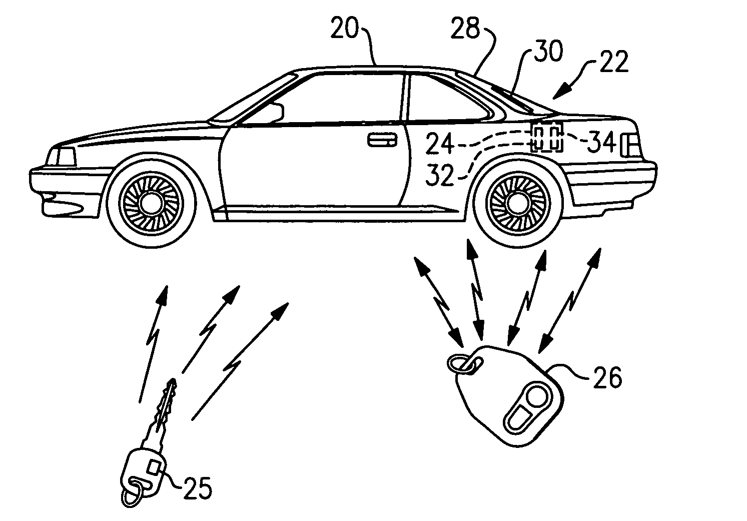
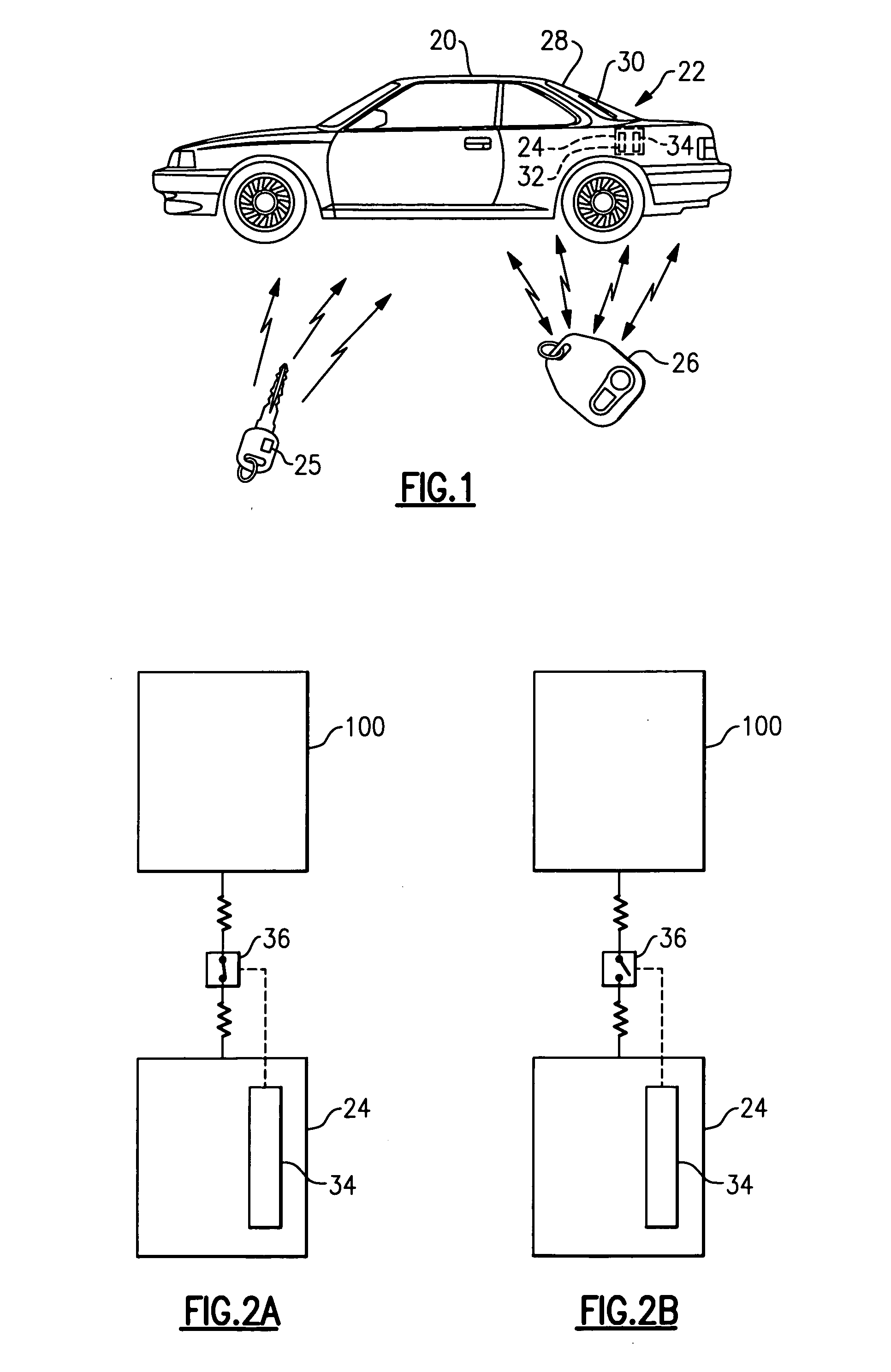
[0013] Referring to FIG. 1, a vehicle 20 is equipped with multiple remote signal communication systems 22. The present invention is described in terms of a vehicle 20 that includes both a passive entry and starting system (PASE) and a remote keyless entry system (RKE). Although the present invention is described in terms of a PASE system and an RKE system, it should be understood that the vehicle 20 may be equipped with any combination and number of remote signal communication systems 22.

[0014] The vehicle 20 includes a receiver module 24. The receiver module 24 communicates with transmitters 25, 26 of the PASE system and the RKE system. The PASE system transmitter is preferably a smart key 25. The transmitter of the RKE system is preferably a key fob 26. In one example, the receiver module 24 is a radio frequency (RF) receiver such that the transmitters 25, 26 of the PASE system and the RKE system communicate with the receiver module 24 by communicating RF signals. Although the re...


PUM


Abstract

A method of controlling the signal sensitivity of a receiver module of a remote signal communication system includes initializing a PASE function and actuating a switch from a first position to a second position. The second position represents an open switch wherein either an external antenna or a LNA circuit or both are shut off. The switch is returned to a first position in response to completion of a PASE command.

Description

CROSS REFERENCE TO RELATED APPLICATIONS [0001] This application claims priority to U.S. Provisional Application No. 60 / 686,069 filed May 27, 2005 and U.S. Provisional Application No. 60 / 683,540, filed May 20, 2005.BACKGROUND OF THE INVENTION [0002] This invention generally relates to remote signal communication systems, and more particularly to a method of controlling the signal sensitivity of a remote signal communication system during passive authentication. [0003] A variety of remote signal communication systems are used in vehicles. Radio frequency (RF) signals have become a communication mode of choice in a number of systems of this type. Examples include remote keyless entry systems (RKE) and passive entry and starting systems (PASE). Such systems typically include a handheld transmitter, such as a key fob or ā€œsmart cardā€, which provides a signal to a receiver module located on the vehicle. The receiver module actuates a vehicle system in response to transmissions received fro...

Claims


Application Information

Patent Timeline
23 Nov 2006
Publication
US20060261925A1
IPC
G05B19/00; B60R25/04
CPC
B60R25/04; B60R25/24; G07C2209/63; G07C2009/00793; G07C9/00309
Inventors
BAUMGARTNER, JOSEF; OSTRANDER, GERALD L.