Small multi-mode antenna and rf module using the same

a multi-mode, small technology, applied in the structure of radiating elements, elongated active elements, resonance antennas, etc., can solve the problems of insatiable portability for users, difficult to apply semiconductor integration circuit technology, and large terminal dimensions, so as to achieve small and less costly rf modules, less costly and small multimedia wireless apparatus

Inactive Publication Date: 2006-11-23
HITACHI LTD
View PDF10 Cites 31 Cited by
  • Summary
  • Abstract
  • Description
  • Claims
  • Application Information

AI Technical Summary

Benefits of technology

[0012] If, in such multi-mode antenna, a same feeding point (input-output terminal) can be set up for electromagnetic waves with different frequencies, RF circuits that process multiple frequencies are allowed to share the single feeding point. In consequence, semiconductor integration circuit technology can be applied and, therefore, RF circuit downsizing can be achieved and a small and less costly RF module compatible with multiple frequencies can be realized.
[0013] Objects of the present invention are to provide a small multi-mode antenna in which a single feeding point can be used commonly for multiple frequencies in order to realize a less costly and small multimedia wireless apparatus, and to provide a small RF module using the multi-mode antenna.

Problems solved by technology

Because the frequencies of electromagnetic waves that are used for services in terms of normal ubiquitous information transmission are limited to a range from a few hundred MHz to a few GHz due to the limitation of their free space propagation characteristic, the antennas must be separated each other by a distance of a few tens of centimeters to a few meters.
Consequently, the dimension of the terminal becomes large and portability for the user is not satisfied.
For this reason, it is difficult to apply semiconductor integration circuit technology and there arises a problem of high-cost RF circuits as well as the increased dimensions of the terminal.
Consequently, transmission loss of the RF cable in the current situation reaches a few dB / m.
With the use of such RF cable, power consumed by the RF circuit increases.
This causes a significant decrease in use duration of the terminal providing ubiquitous information services or a significant increase in the terminal weight due to increased battery volume and poses a problem of significantly degrading the usability for the user of the terminal.
Thus, it is difficult to integrate both, which makes a bottleneck in downsizing the wireless apparatus.

Method used


Image

  • Small multi-mode antenna and rf module using the same
  • Small multi-mode antenna and rf module using the same
  • Small multi-mode antenna and rf module using the same

Examples


Embodiment Construction

[0047] The multi-mode antenna and the RF module using it in accordance with the present invention will be described hereinafter more fully with reference to several embodiments shown in the drawings. In the drawings, functionally identical components are assigned the same reference numbers and their explanation is not repeated.

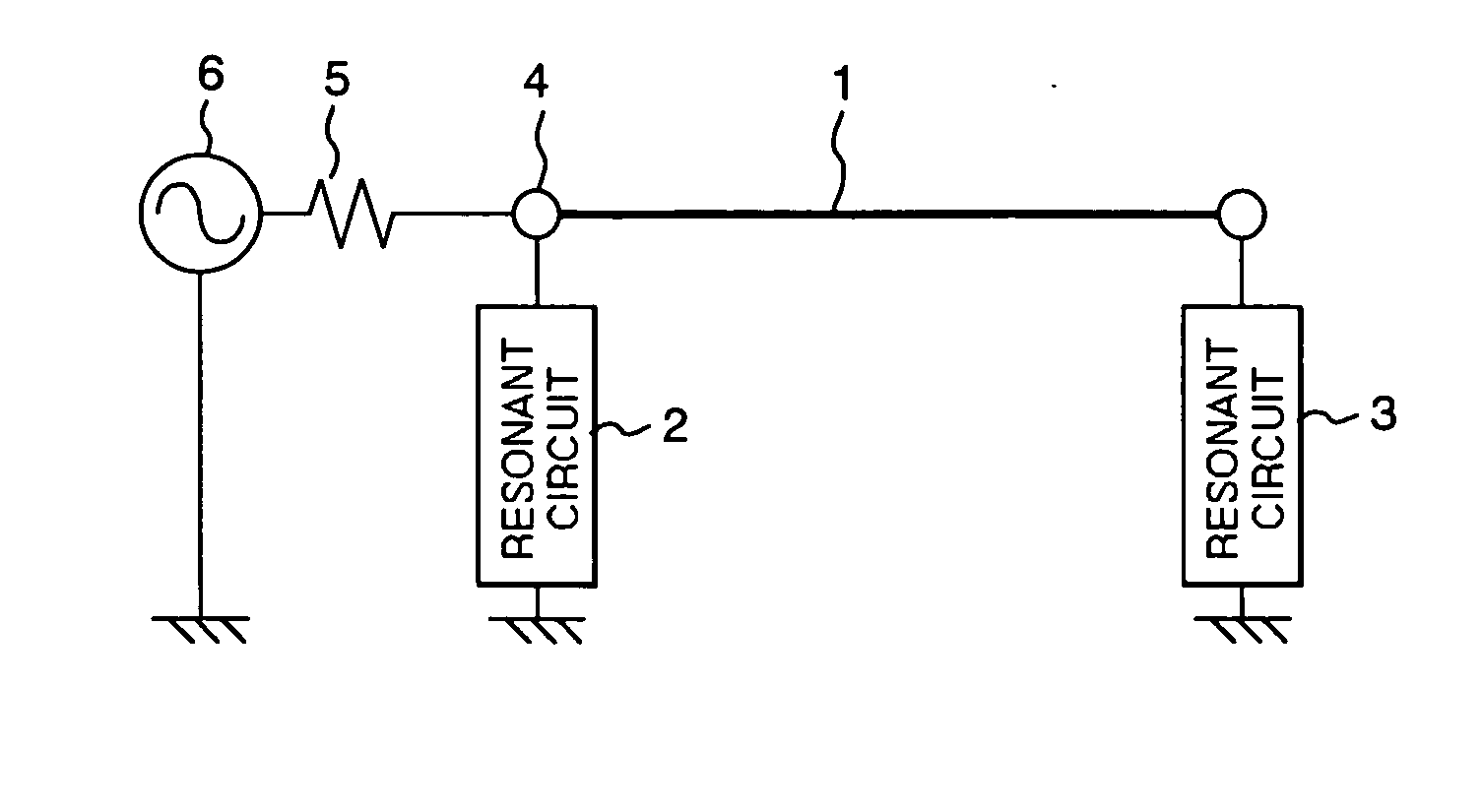
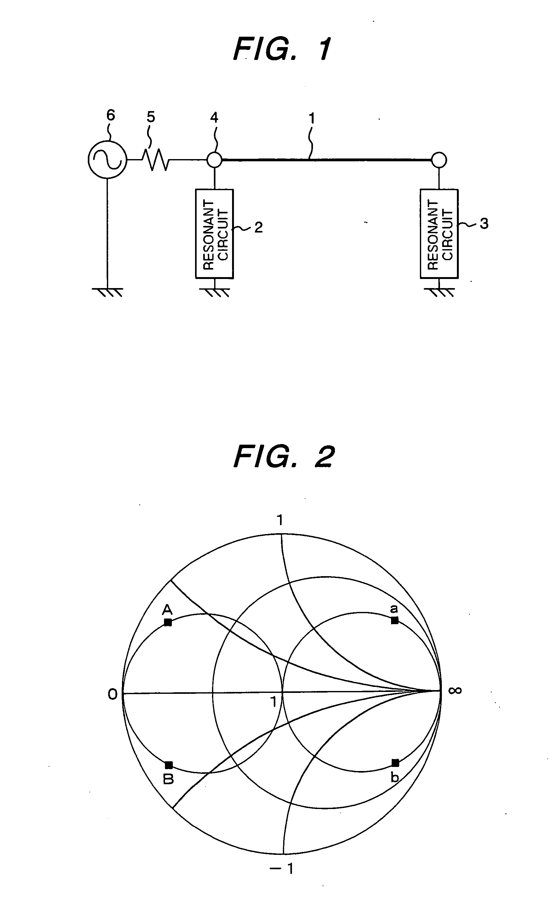
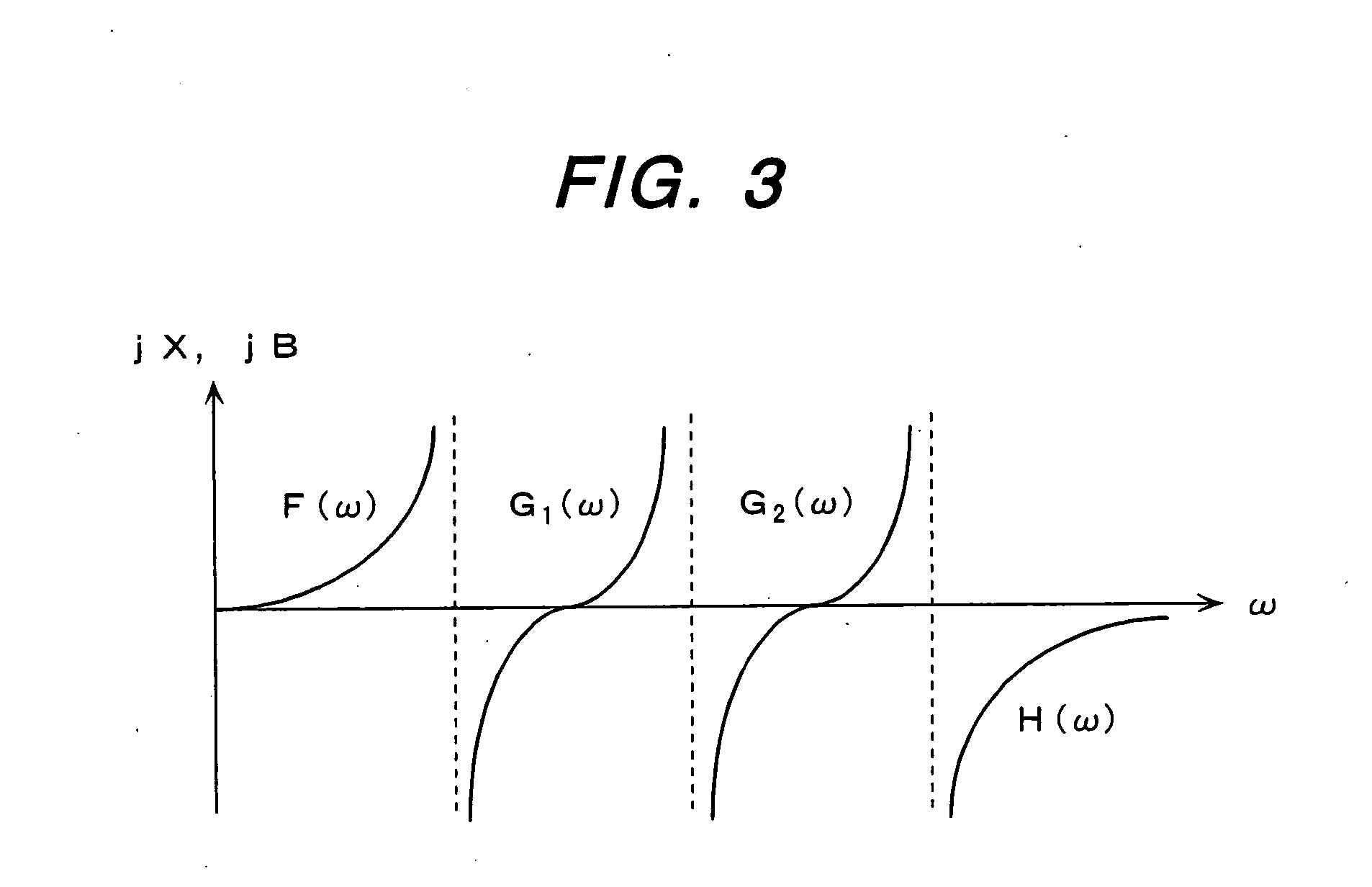
[0048] One embodiment of the present invention is described with FIGS. 1, 2, and 3. FIG. 1 is a structural diagram showing the components of a multi-mode antenna embodiment of the present invention and their connections. FIG. 2 and FIG. 3 are a Smith chart and a reactance function characteristic graph chart, respectively, to explain the characteristics of resonant circuits in FIG. 1.

[0049] In FIG. 1, the antenna has a structure in which a first one-port resonant circuit 2 is connected between one end of a radiating conductor 1 which radiates electromagnetic waves with multiple frequencies and a ground potential point, a second one-port resonant circuit 3 is ...


PUM


Abstract

A small multi-mode antenna in which a single feeding point can be used commonly for multiple frequencies and an RF module using such antenna for use in less-costly and small multimedia wireless apparatus is provided. The antenna is configured such that a single feeding point 4 which is common for multiple frequencies is set up at one end of a radiating conductor 1, a first one-port resonant circuit 2 is connected to the one end thereof, and a second one-port resonant circuit 3 is connected to the other end of the radiating conductor 1. With a conductance component of admittance in view from the feeding point 4 toward free space equaling the characteristic admittance in the RF circuit, a susceptance component of the admittance is canceled out by the resonant circuit 2 connected to the feeding point 4 for multiple frequencies.

Description

TECHNICAL FIELD [0001] The present invention relates to an antenna of wireless apparatus that provides the user with multi-media services and a RF (Radio Frequency) module including the antenna. In particular, for use in multimedia wireless apparatus that implements a plurality of services by information transmission through the media of electromagnetic waves with different frequencies, the invention relates to a multi-mode antenna applied to the wireless apparatus and a multi-mode compatible RF module including the antenna. BACKGROUND ART [0002] Multimedia services providing services in terms of transferring and providing various kinds of information by way of radio transmission are getting more active lately and a great number of wireless apparatuses have been developed and put into practical use. These services are diversified year after year, involving telephones, TVs, Local Area Networks (LANs), etc. End users are required to have different wireless apparatuses for different se...

Claims


Application Information

Patent Timeline
Patent Type & Authority Applications(United States)
IPC IPC(8): H01Q1/50H01Q1/38H01Q1/24H01Q5/10H01Q5/321H01Q5/328H01Q9/04H01Q9/30H04B1/40
CPCH01Q1/241H01Q1/38H01Q5/314H01Q9/0442H01Q9/30H01Q5/00
Inventor TAKEI, KEN
Owner HITACHI LTD
Why Eureka
Try Eureka