
Current detection circuit applied to sic field effect transistor

a current detection and transistor technology, applied in the direction of efficient power electronics conversion, measurement using digital techniques, instruments, etc., can solve the problems of large volume of coaxial shunt resistor, high manufacturing cost, and inconvenient wide-application coaxial shunt resistor, etc., to achieve the effect of high-power high-frequency current detection efficiency

Pending Publication Date: 2021-11-25
XI AN JIAOTONG UNIV
View PDF3 Cites 1 Cited by
  • Summary
  • Abstract
  • Description
  • Claims
  • Application Information

AI Technical Summary

Benefits of technology

The present invention provides a current detection circuit for a SiC field effect transistor that overcomes the disadvantages of prior art. The circuit effectively avoids the influence of parasitic inductance on the detection performance of the current sampling resistor and is less costly and smaller. The circuit includes a compensating branch consisting of a compensating resistor and a compensating inductor, which form a compensating branch with a much larger value than the total parasitic inductance and a much larger value than the sampling resistor. The circuit also includes a branch consisting of the current sampling resistor and the total parasitic inductance, which is connected in parallel with the compensating branch to compensate for the total parasitic inductance. The circuit is smaller and can effectively avoid the influence of parasitic inductance on the detection performance of the current sampling resistor.

Problems solved by technology

A subsequent technical problem is how to detect the switching performance of a SiC MOSFET.
Due to a coaxial structure and a manufacturing process, the coaxial shunt resistor is too large in volume and high in manufacturing cost, so the coaxial shunt resistor is not suitable for wide application.
Although the Kelvin four-wire connection can avoid the influence of external parasitic inductance on current detection, the influence of internal parasitic inductance cannot be ignored, so it is not very suitable for high-power and high-frequency current detection.

Method used


Image

  • Current detection circuit applied to sic field effect transistor
  • Current detection circuit applied to sic field effect transistor
  • Current detection circuit applied to sic field effect transistor

Examples


Embodiment Construction

lass="d_n">[0040]To make the objectives, technical solutions, and advantages of implementations of the present invention clearer, the technical solutions in the implementations of the present invention are clearly and completely described below with reference to the drawings in the implementations of the present invention. The following detailed description of the implementations of the present invention provided in the drawings is not intended to limit the scope of the present invention for which protection is sought, but merely to indicate selected implementations of the present invention.

[0041]Specific embodiments of the present invention are described in detail below with reference to the drawings.

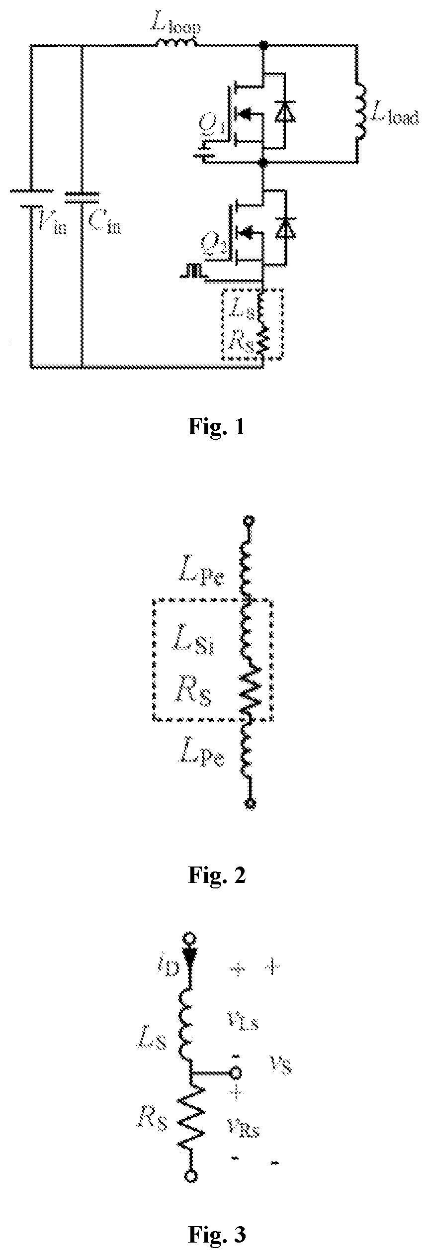
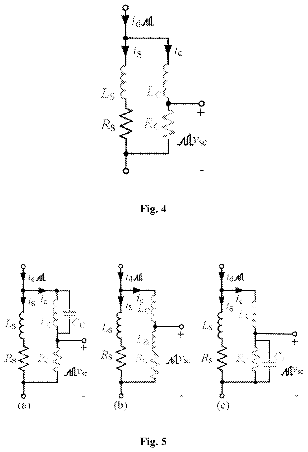
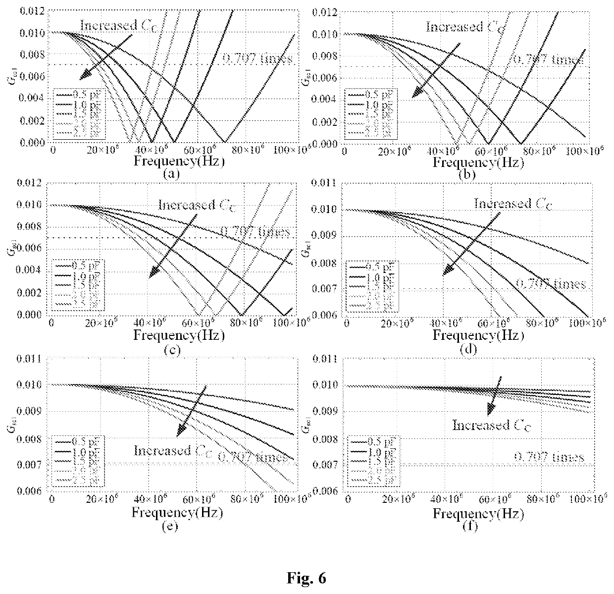
[0042]Referring to FIG. 1 to FIG. 4, an embodiment of the present invention provides a current detection circuit applied to a SiC field effect transistor, the current detection circuit including:

[0043]a current detection loop and an acquisition loop on the current detection loop.

[0044]...


PUM


Abstract

The present invention provides a current detection circuit applied to a SiC field effect transistor. The current detection circuit includes a current detection loop and an acquisition loop on the current detection loop. The current detection loop includes a voltage source, a capacitor, a first SiC field effect transistor, a second SiC field effect transistor, and a sampling resistor. The first SiC field effect transistor is connected to a power signal. The second SiC field effect transistor is connected to a pulse signal. The acquisition loop includes a compensating resistor and a compensating inductor. The compensating resistor and the compensating inductor are connected in series and then connected in parallel at two ends of the sampling resistor to counteract the influence of total parasitic inductance in the current detection loop.

Description

CROSS-REFERENCE TO RELATED APPLICATIONS[0001]This application claims priority to Chinese Application No. 202010438104.6, filed on May 21, 2020, entitled “Current detecting circuit and detecting method”. These contents are hereby incorporated by reference.TECHNICAL FIELD[0002]The present invention relates to the field of SiC field effect transistors, and particularly to a current detection circuit applied to a SiC field effect transistor.BACKGROUND[0003]A power semiconductor device is a key component of power electronic equipment. In 1957, the General Electric developed the first thyristor, which marked the birth of a power electronic technology. Since the 1990s, with the continuous in-depth research and understanding of SiC materials and the gradual improvement of SiC epitaxy technologies, power electronic devices based on SiC materials have been commercialized and are gradually used in some application occasions where original silicon devices are not suitable, such as high-temperat...

Claims


Application Information

Patent Timeline
IPC IPC(8): G01R19/25
CPCG01R19/25G01R19/0092G01R19/16519G01R31/2621Y02B70/10
Inventor WANG, LAILIYANG, CHENGZILI, HUAQINGLIU, XINGSHUOYU, LONGYANGPEI, YUNQINGGAN, YONGMEIYANG, XU
Owner XI AN JIAOTONG UNIV
Learn More