This helps you quickly interpret patents by identifying the three key elements:
Problems solved by technology
Method used
Benefits of technology
Benefits of technology
[0006] An object of the present invention is to provide a display apparatus which effectively suppresses a deterioration in display quality.
Problems solved by technology
As a result, an original gradation cannot be provided to impair a display quality in some cases.
Method used
Image
Click on the blue label to locate the original text in one second.
Reading with bidirectional positioning of images and text.
Examples
example 1
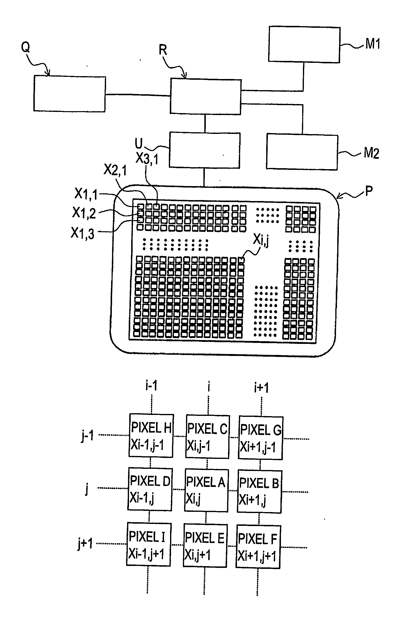
[0074] A display apparatus shown in FIGS. 1(a) and 1(b) was prepared in the following manner. The display apparatus included, as a display device P, an electrophoretic display device P1, as shown in FIGS. 8(a) and 8(b) having a matrix of pixels with 300 rows and 250 columns.
[0075] The electrophoretic display device P1 included a pair of 1.1 mm-thick glass substrates 1a and 1b. In a spacing between these substrates 1a and 1b, a plurality of microcapsules 5 each containing a dispersion liquid 2 and electrophoretic particles 3 were prepared through a composite coacervation method and disposed. The dispersion liquid 2 was colored black with a dye, and the electrophoretic particles 3 were formed of white titaniumoxide. A electrode 4b on an observer (viewer) side (“common electrode”) was formed of transparent ITO (indiumtinoxide), and an opposite electrode 4a (“pixel electrode”) was formed of Al (aluminum). Further, to each of the pixel electrodes 4a, a TFT (not shown) was connected s...
example 2
[0088] In this example, rewriting voltages for all the pixels were determined in the same manner as in Example 1 by using the same apparatus as in Example 1, and were stored in a memory.
[0090] More specifically, i=1, j=1 and k=1 are set (S11), and values of the rewriting voltages for a correction pixel Xi,j and its adjacent pixels Xi+1,j; Xi,j−1; Xi−1,j; and Xi,j+1 were extracted from the memory (S12).
[0091] Next, a rewriting voltage for the correction pixel Xi,j is obtained by making reference to table data (S13). The obtained rewriting voltage value is digital information providing a voltage value, which is stored in a predetermined memory.
[0092] Then, when “i=250 an j=300” are not satisfied, checking of “i=250” is carried out (S14 and S15). In the case where “i=250” is not satisfied, i=i+1 and j=j are set (S15 and S17), and a correction value of rewriting voltage is obtained (S12 and S13). This data pr...
example 3
[0101] In this example, a display apparatus shown in FIG. 1 including a liquid crystal display device P2 shown in FIG. 11 was prepared.
[0102] As a pair of substrates 11a and 11b, a 1.1 mm-thick glass substrate was used. An electrode 14b on an observer side was formed of transparent ITO and an opposite electrode 14a was formed of Al. Other structural members and data processing were the same as those in Example 1.
[0103] As a result, according to this example, it was possible to effect display at an appropriate gradation.
PUM
Abstract
In a display apparatus using charged electrophoretic particles, being controlled by an electric field at the pixels, in some cases the charged particles fail to display a desired gradation level even when a voltage is applied to the pixel with the intention of providing the desired gradation level. In such cases, correction values for all the gradation levels are obtained in advance by experiment, and then a corrected voltage is applied to the pixel, whereby it is possible to provide a desired gradation by compensating an influence of an electric field at adjacent pixels.
Description
TECHNICAL FIELD [0001] The present invention relates to a display apparatus which includes a plurality of pixels arranged in a matrix and effects gradation display at each pixel. BACKGROUND [0002] In recent years, as a display device for displaying various information, an electrophoretic display device for displaying information by controlling a position of electrophoretic particles (charged migration particles) or a liquid crystaldisplay device for displaying information by applying a voltage to a liquid crystal has received attention. [0003] These display devices are constituted by a matrix of pixels each at which gradation display can be effected. [0004] FIGS. 12(a) and 12(b) are respectively a sectional view showing an example of a structure of a conventional electrophoretic display device described in Japanese Laid-Open Patent Application (JP-A) No. 2000-258805. This electrophoretic display device includes a pair of substrates 21a and 21b provided with electrodes 24a and 24b, ...
Claims
Application Information
Patent Timeline
Application Date:The date an application was filed.
Publication Date:The date a patent or application was officially published.
First Publication Date:The earliest publication date of a patent with the same application number.
Issue Date:Publication date of the patent grant document.
PCT Entry Date:The Entry date of PCT National Phase.
Estimated Expiry Date:The statutory expiry date of a patent right according to the Patent Law, and it is the longest term of protection that the patent right can achieve without the termination of the patent right due to other reasons(Term extension factor has been taken into account ).
Invalid Date:Actual expiry date is based on effective date or publication date of legal transaction data of invalid patent.

