Folding and adjusting hinge for stabilized equipment support

a technology for equipment supports and hinges, applied in the direction of machine supports, instruments, building scaffolds, etc., can solve the problems of reducing the focal length of the lens that can be used, reducing the precision and consistency of the balance, and inherently less rigid plastic versions. achieve the effect of inertial stability

Active Publication Date: 2006-11-23
BROWN GARRETT
View PDF20 Cites 44 Cited by
  • Summary
  • Abstract
  • Description
  • Claims
  • Application Information

AI Technical Summary

Benefits of technology

[0019] Folding is accomplished by displacing the lower spar around a hinge axis to swing up to be tucked under the camera mounting portion of the stabilizer. Preferably the upper and lower spars are curved and positioned in or parallel to a plane that includes the camera's lens axis and is perpendicular to the camera's mounting surface. This configuration in particular lends itself to the folding and balancing hinge assembly providing one or more attachment points for weights or camera equipment, such as a video monitor, to provide additional inertial stability.
[0025] Embodiments of the invention may provide attachments at the double-acting hinge and at the extremity of the lower spar for either weights or camera equipment masses which, along with the mass of the camera, provide increased inertial stability in three, mutually-perpendicular axes.

Problems solved by technology

That plastic version, however, was inherently somewhat less rigid, and therefore was less precisely and consistently balanced, than the original aluminum prototype as detailed in the above-mentioned U.S. Pat. No. 4,946,272.
Such flexibility is deleterious to camera stability and tends to limit the focal lengths of the lenses that can be employed, since the energy of any vibration within or between components is conserved in the entire assembly and produces sympathetic vibrations that may be apparent in the camera's images, particularly as the lens is ‘zoomed in’ toward the telephoto end of its range.
Though rigid, the aluminum prototype, was not adapted to be conveniently (or repeatably) folded.
Unlocking its hinge to raise the lower spar up beneath the camera mounting platform caused its balance position (achieved by trial and error) to be lost.
Thus, these various approaches, and other variously simplistic attempts at hand-held camcorder stabilizers, have failed to provide an apparatus which could conveniently, repeatably and progressively be adjusted to stabilize a range of camcorders of various weights, and which could also fold and unfold in a manner that alternately sought either the singular best folding position or the elected, balanced operating position for the chosen camcorder and its associated equipment.

Method used


Image

  • Folding and adjusting hinge for stabilized equipment support
  • Folding and adjusting hinge for stabilized equipment support
  • Folding and adjusting hinge for stabilized equipment support

Examples


Embodiment Construction

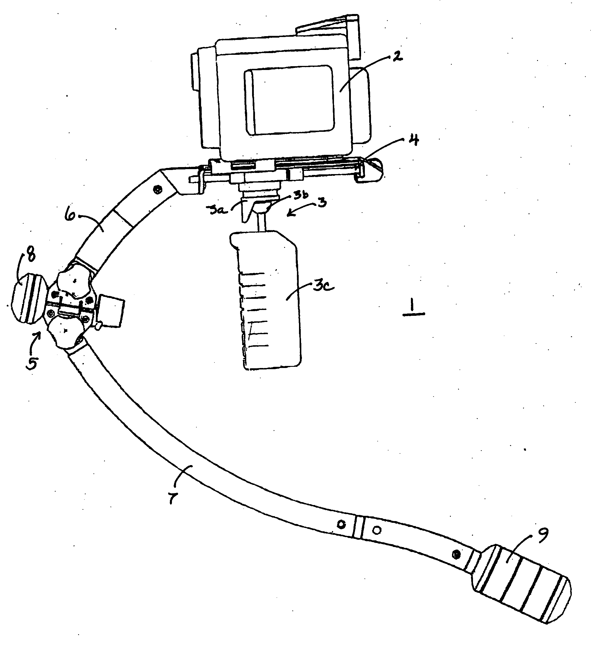
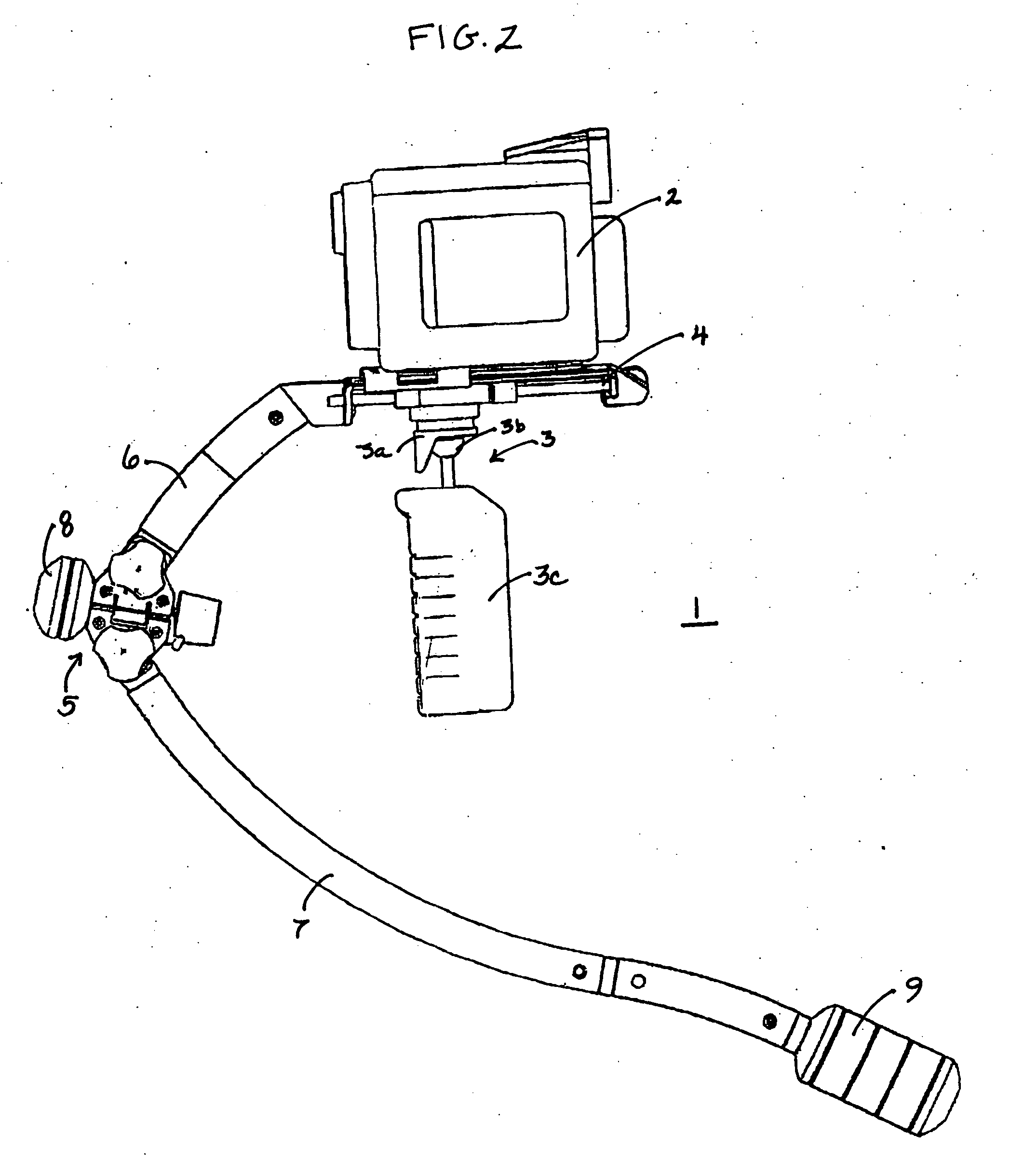
[0051] Embodiments of the invention provide a double-acting hinge assembly that adjustably alters the fore / aft pivot angle between an upper and lower spar of a hand-supported camera stabilizing apparatus and also alters the lateral pivot angle of the spars by half as much, and therefore provides that the folded position of the lower spar consistently docks beneath the camera mounting assembly.

[0052] In an illustrative embodiment of the invention, a simple, light and rigid clamping mechanism is provided to interconnect the various components of a hand-held camera stabilizing support, including the camera stage, the upper spar, the hinge pivots, the lower spar, and the counterbalancing weights and / or counterbalancing equipment.

[0053] These and other characteristics are achieved in accordance with embodiments of the invention by providing a novel double-acting hinge mechanism, which simultaneously adjusts the vertical balancing angle between the upper and lower counterbalancing spars...


PUM


Abstract

An improved equipment stabilizing support apparatus having an upper spar associated with the equipment and a lower spar connected by a double-acting type hinge that provides angular displacement between the upper and lower spars to adjustably balance equipment, and angular displacement around a second axis to allow folding of the lower spar toward the upper spar to an optimum closed configuration regardless of the adjusted balancing position.

Description

[0001] This application is based on, and claims priority to, provisional application Ser. No. 60 / 672,138, having a filing date of Apr. 15, 2005, and entitled, Folding and Adjusting Hinge for Stabilized Equipment Support.FIELD OF THE INVENTION [0002] The invention is directed to stabilized equipment supports, and more particularly to hinges for supports. BACKGROUND OF THE INVENTION [0003] This invention relates generally to equipment supports, and more particularly to an improvement in portable handheld equipment adapted to stabilize compact video camcorders. [0004] Mobile film or video cameras typically require angular and spatial stability in order to obtain smooth, high-quality results. The Steadicam® portable camera stabilizing device, which has become a de facto standard in the TV and movie industry, was developed to permit stable ambulatory videography or cinematography by an operator. The inventor's U.S. Pat. No. 4,017,168 (Re. 32,213) is directed to a version of the Steadicam...

Claims


Application Information

Patent Timeline
Patent Type & Authority Applications(United States)
IPC IPC(8): G03B21/00G03B17/00
CPCF16M13/04G03B17/56G03B17/02F16M11/14F16M2200/041G03B17/561G03B17/563G03B17/00G03B21/14G03B21/00F16M13/00
Inventor BROWN, GARRETT W.SACKSTEDER, ANTHONY D.
Owner BROWN GARRETT
Why Eureka
Try Eureka