
Method and system for efficient flow control in a spot beam satellite system

a satellite system and spot beam technology, applied in the field of communication systems, can solve the problems of not always, or even ever, being able to accept such traffic, consuming additional network bandwidth, and data loss

Active Publication Date: 2006-11-23
HUGHES NETWORK SYST
View PDF29 Cites 44 Cited by
  • Summary
  • Abstract
  • Description
  • Claims
  • Application Information

AI Technical Summary

Benefits of technology

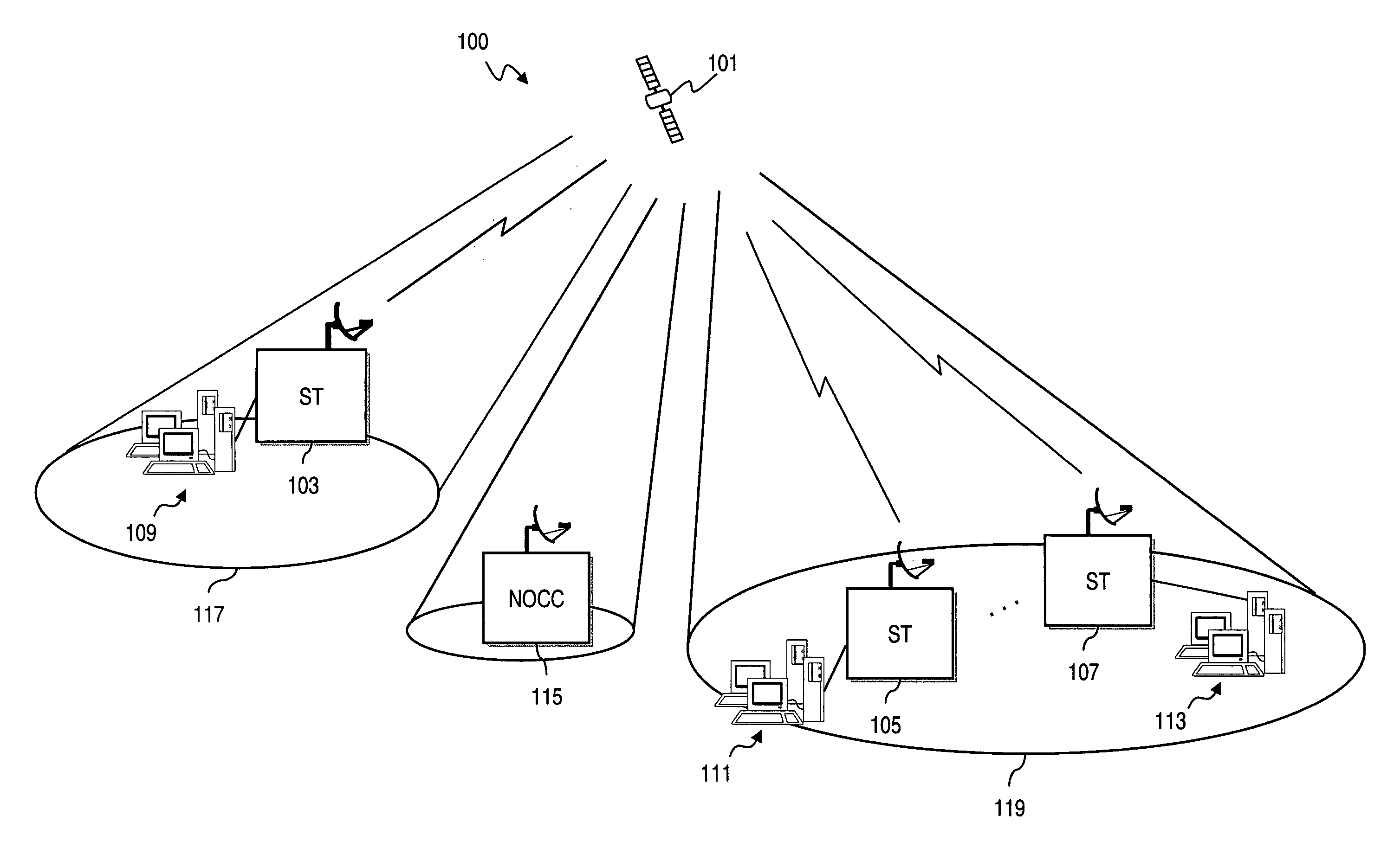
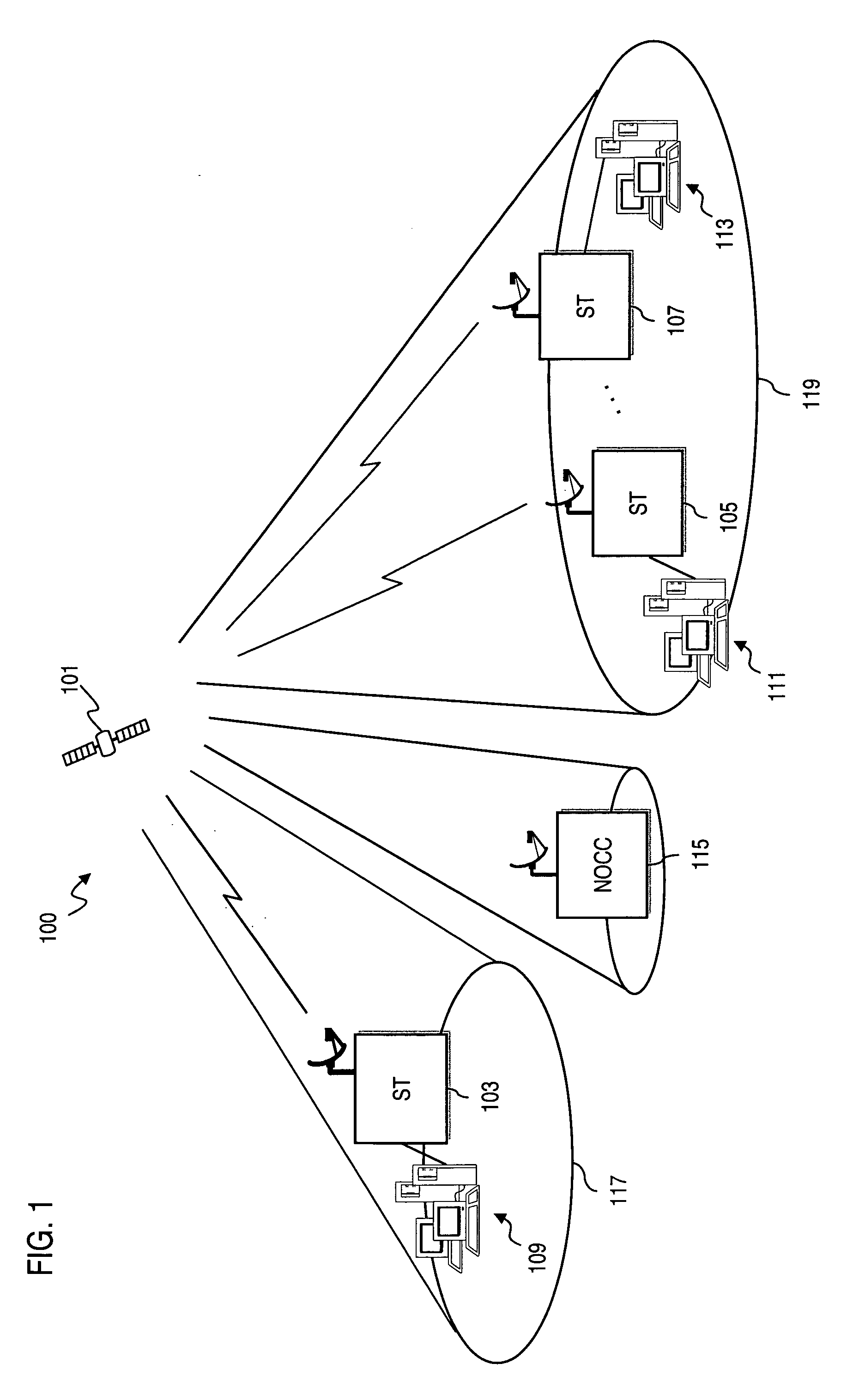
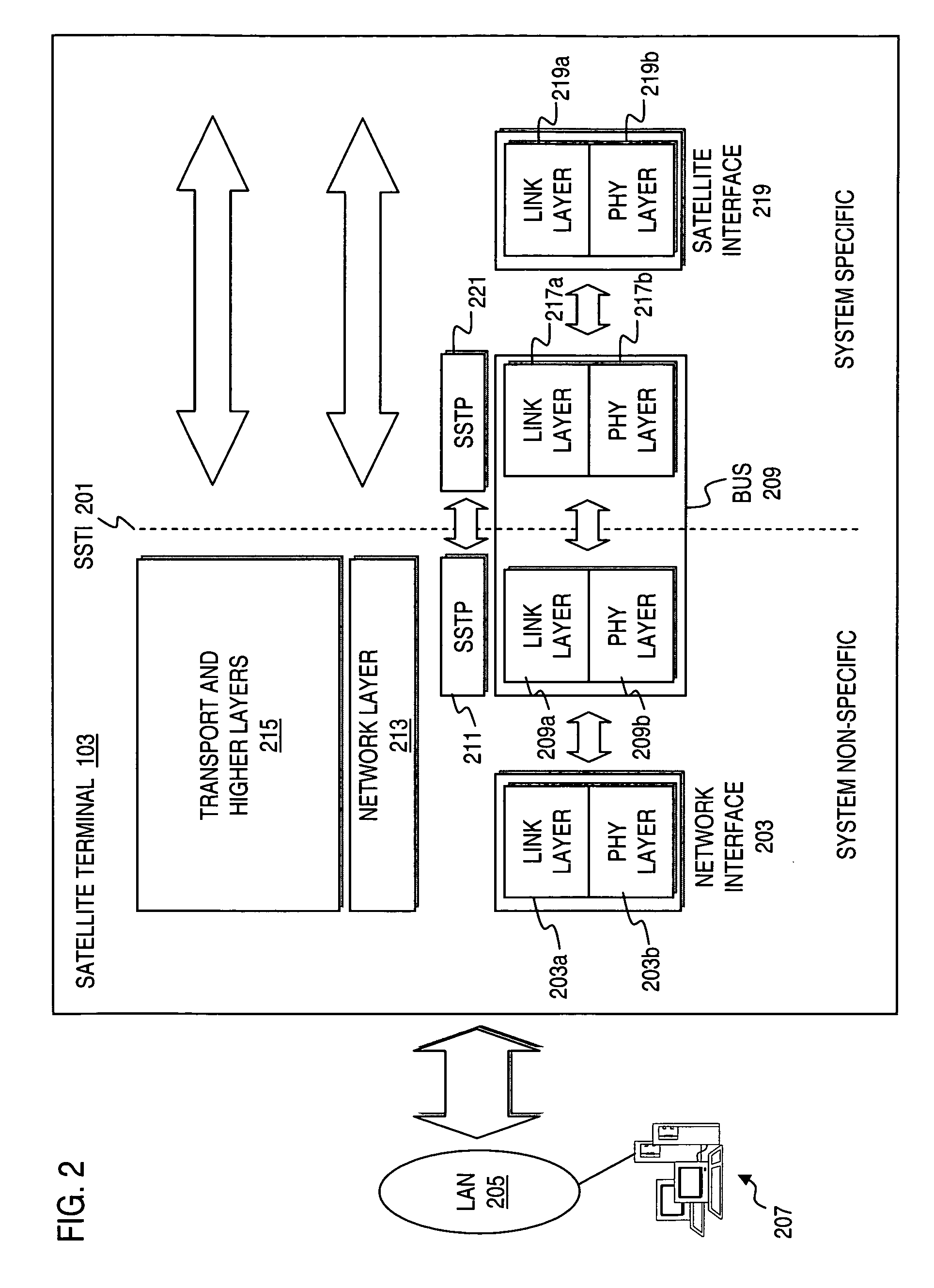
[0007] According to one aspect of the present invention, a method for providing flow control in a radio communication system is disclosed. The method includes receiving a dataflow from a host, and storing the dataflow in a queue of a system non-specific side of a transport interface. The method also includes determining whether the dataflow can be flow controlled, and if the dataflow can be flow controlled, obtaining a credit allocation corresponding to a queue of a system specific side of the transport interface. The system specific side supports a signaling function that is based on a transmission characteristic of the radio communication system. The system specific queue is designated for storing data to be transmitted over the radio communication system. The credit allocation specifies an amount of the dataflow to be sent to the system specific queue. The method further includes transferring the dataflow from the system non-specific queue to the system specific queue for transmission over a communication link established over the radio communication system.
[0008] According to another aspect of the present invention, an apparatus for providing flow control in a radio communication system is disclosed. The apparatus includes a transport interface including a system non-specific side that is associated with a queue for storing a dataflow from a host. The interface also in

Problems solved by technology

This other, or second, stage may not always, or even ever, be able to accept such traffic from the first stage at the maximum possible discharge rate by the first stage towards the second stage.
If the destination were to be overwhelmed in such fashion, data would be lost, and additional network bandwidth would be consumed for any necessary retransmissions.
Satellite communication systems face the added challenge of delay stemming from signal propagation over great distances.
Thus, retransmission is extremely costly.
However, because of spectral limitations, satellite communication systems are bandwidth constrained relative to terrestrial networks.
In addition, modern data applications, which can include multimedia and real-time applications, often demand high-speed transfer of large amounts of data, such that a satellite communication system would likely be unable to service such great demands all at once.

Method used


Image

  • Method and system for efficient flow control in a spot beam satellite system
  • Method and system for efficient flow control in a spot beam satellite system
  • Method and system for efficient flow control in a spot beam satellite system

Examples


Embodiment Construction

[0018] A method, device, and software for providing credit-based flow control in a radio communication system are described. In the following description, for the purposes of explanation, numerous specific details are set forth in order to provide a thorough understanding of the present invention. It is apparent, however, to one skilled in the art that the present invention may be practiced without these specific details or with an equivalent arrangement. In other instances, well-known structures and devices are shown in block diagram form in order to avoid unnecessarily obscuring the present invention.

[0019] The present invention, according to one embodiment, controls dataflow at a transport interface within a satellite terminal (ST) operating in a satellite communication system that supports spot beams. The interface has a system non-specific side that supports signaling functions that are independent from the satellite communication system. The interface also has a system specif...


PUM


Abstract

An approach for providing flow control in a radio communication system is disclosed. A request from a non-satellite system specific side of a transport interface is made to a system specific side of the transport interface for a flow control allocation that specifies an amount of data to be stored in a queue of the system specific side of the transport interface. The system specific side supports a signaling function that is based on a transmission characteristic of the radio communication system. The flow control allocation is generated based upon availability of the queue, wherein the destination address is a link layer address of the satellite communication system. This arrangement has particular applicability to a satellite network (e.g., Very Small Aperture Terminal (VSAT) network) that provides data communication services.

Description

FIELD OF THE INVENTION [0001] The present invention relates to a communications system, and more particularly to flow control. BACKGROUND OF THE INVENTION [0002] In a communications system, flow control regulates the flow of communications traffic from one stage of the communications system to another stage. This other, or second, stage may not always, or even ever, be able to accept such traffic from the first stage at the maximum possible discharge rate by the first stage towards the second stage. The flow control mechanism ensures that a source of a dataflow does not overwhelm a destination, which could occur by the source transmitting data to the destination at a rate exceeding that which the destination can process. If the destination were to be overwhelmed in such fashion, data would be lost, and additional network bandwidth would be consumed for any necessary retransmissions. Satellite communication systems face the added challenge of delay stemming from signal propagation ov...

Claims


Application Information

Patent Timeline
IPC IPC(8): H04J1/16H04L12/56
CPCH04B7/18582H04L47/10H04L47/39H04L47/2441H04L47/30H04L47/14H04W8/04
Inventor FRIEDMAN, DANIELTORRES, ROBERTSTEVENS, PATRICKSCHWEINHART, CRAIGKANNAN, MANGALAARUR, DEEPAKLIN, PETERBUTEHORN, MATTHEWBURRELL, KEN
Owner HUGHES NETWORK SYST
Learn More