Relative humidity profile control strategy for high current density stack operation

a technology of relative humidity and stack operation, which is applied in the direction of fuel cells, electrical equipment, electrochemical generators, etc., can solve the problems of limiting the performance of the fuel cell stack, affecting the performance of the fuel cell, and high current density operation, and achieve the effect of high current density operation of the fuel cell stack

Active Publication Date: 2006-11-23
GM GLOBAL TECH OPERATIONS LLC
View PDF16 Cites 39 Cited by
  • Summary
  • Abstract
  • Description
  • Claims
  • Application Information

AI Technical Summary

Benefits of technology

[0006] The present invention provides a control strategy that results in a relative humidity profile, i.e. the way the relative humidity changes along the flow path of the cathode reactant flowing from inlet to outlet, that is substantially the same or constant regardless of the operational power level of the fuel cell stack. The strategy maintains the relative humidity profile within a range that enables high current density operation of the fuel cell stack. The profile is achieved by adjusting a coolant flow rate through the fuel cell stack to maintain a temperature change across the coolant flow path from inlet to outlet substantially constant regardless of the operational power level of the fuel cell stack.

Problems solved by technology

The level of humidity or hydration of the MEAs affects the performance of the fuel cell.
Too wet of an MEA limits the performance of the fuel cell stack and may prevent high current density operation.
Specifically, formation of liquid water impedes the diffusion of gas to the MEAs, thereby limiting their performance.
The liquid water also acts as a flow blockage reducing cell flow and causing even higher fuel cell relative humidity which can lead to unstable fuel cell performance.
Too dry of an MEA also limits the performance and may prevent high current density operation.
Specifically, as the humidity level decreases the protonic conductivity of the MEA will start to increase (especially near the inlet), resulting in additional waste heat and lower production of electricity.
Furthermore, durability data suggests that large cycling in the moisture content of the MEA that leads to flooded and dried membranes can lead to significant loss in durability due to repeated membrane swelling and shrinking.
Thus, flooded and dry operating conditions limit high current density operation and may reduce the durability of the MEA and the fuel cell.

Method used


Image

  • Relative humidity profile control strategy for high current density stack operation
  • Relative humidity profile control strategy for high current density stack operation
  • Relative humidity profile control strategy for high current density stack operation

Examples


Embodiment Construction

[0017] The following description of the preferred embodiments is merely exemplary in nature and is in no way intended to limit the invention, its application, or uses. As used herein, the term “module” refers to an application specific integrated circuit (ASIC), an electronic circuit, a processor (shared, dedicated or group) and memory that execute one or more software or firmware programs, a combinational logic circuit, or other suitable components that provide the described functionality.

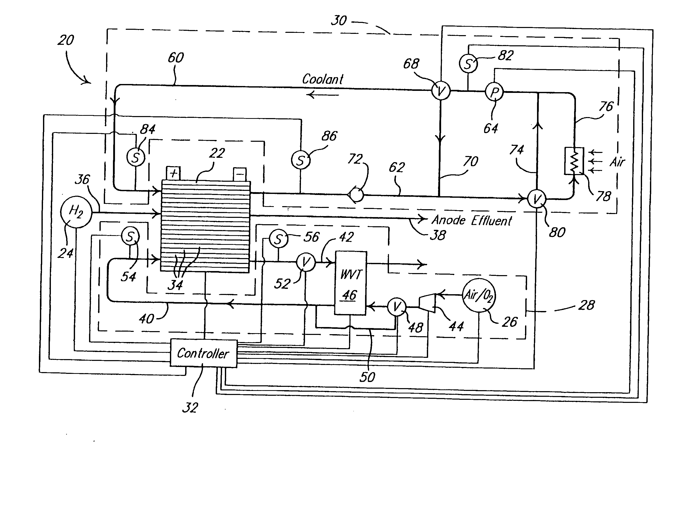
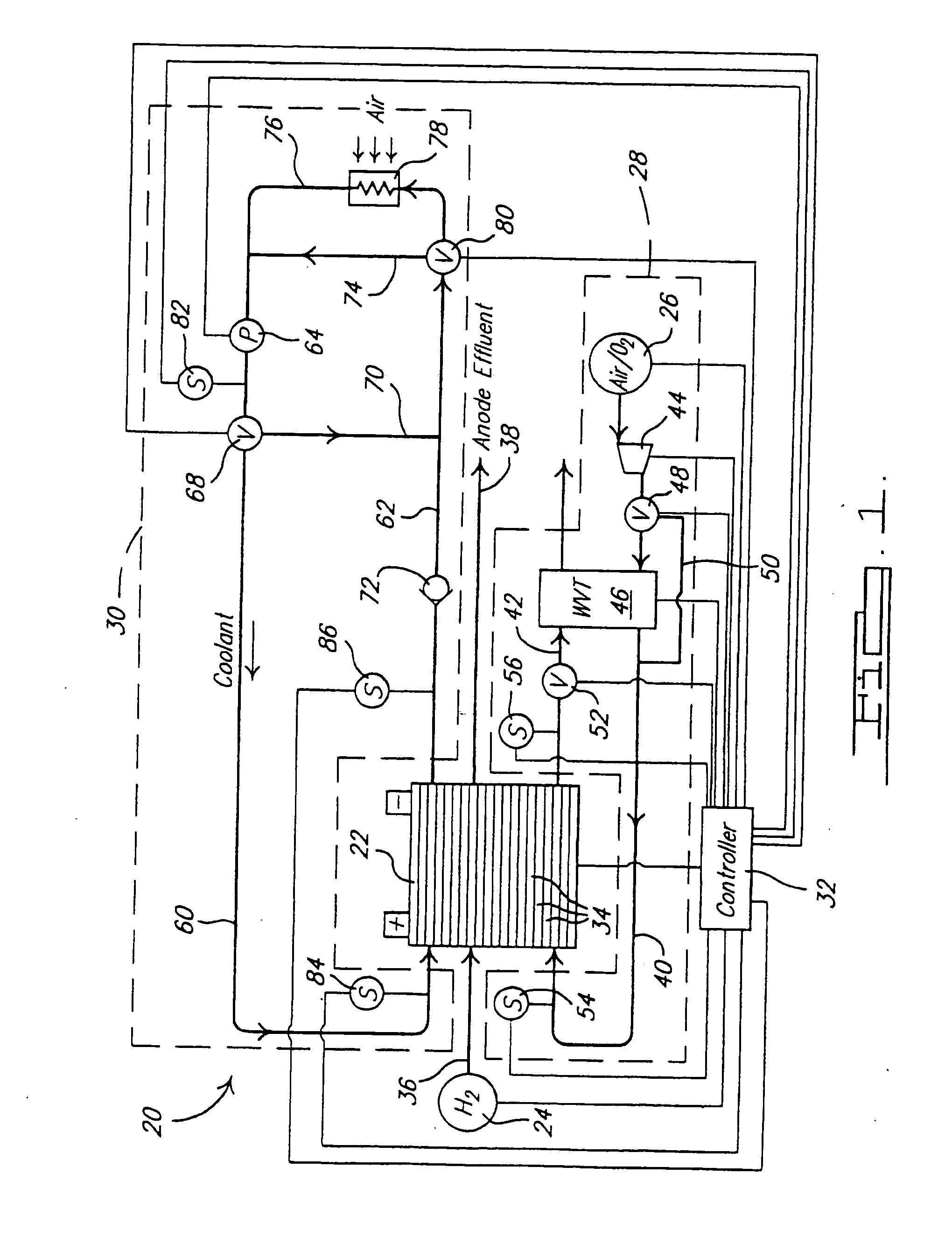
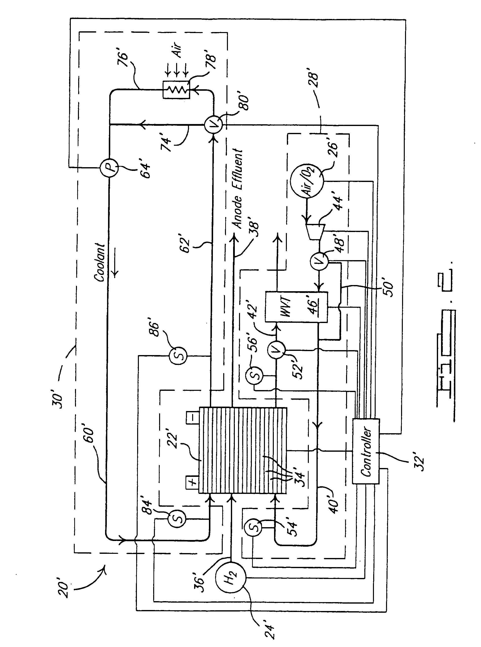
[0018] The present invention is directed to a method of controlling the operation of a fuel cell and / or fuel cell stack so that a desired relative humidity profile is achieved for the membranes in the fuel cell(s). In this regard, the present invention is discussed with reference to specific mechanizations for a fuel cell system having a fuel cell stack therein. It should be appreciated, however, that the mechanizations shown are merely exemplary and that the methods of the present invention are ...


PUM

PropertyMeasurementUnit
inlet pressureaaaaaaaaaa
outlet pressureaaaaaaaaaa

Abstract

A control strategy results in a relative humidity profile that is substantially the same or constant regardless of the operational power level of the fuel cell stack. The strategy maintains the relative humidity profile within a range that enables high current density operation of the fuel cell stack. The profile is achieved by adjusting a coolant flow rate through the fuel cell stack to maintain a temperature change across the coolant flow path from inlet to outlet substantially constant regardless of the operational power level of the fuel cell stack.

Description

FIELD OF THE INVENTION [0001] The present invention relates to fuel cell stacks and, more particularly, to a control strategy to achieve a relative humidity profile for high current density fuel cell stack operation. BACKGROUND OF THE INVENTION [0002] Fuel cells are used as a power source for electric vehicles, stationary power supplies and other applications. One known fuel cell is the PEM (i.e., Proton Exchange Membrane) fuel cell that includes a so-called MEA (“membrane-electrode-assembly”) comprising a thin, solid polymer membrane-electrolyte having an anode on one face and a cathode on the opposite face. The MEA is sandwiched between a pair of electrically conductive contact elements which serve as current collectors for the anode and cathode, which may contain appropriate channels and openings therein for distributing the fuel cell's gaseous reactants (i.e., H2 and O2 / air) over the surfaces of the respective anode and cathode. [0003] PEM fuel cells comprise a plurality of the ...

Claims


Application Information

Patent Timeline
Patent Type & Authority Applications(United States)
IPC IPC(8): H01M8/04
CPCH01M8/04007Y02E60/50H01M8/04291H01M8/04335H01M8/0435H01M8/04358H01M8/04388H01M8/04402H01M8/04417H01M8/04507H01M8/04619H01M8/04723H01M8/04753H01M8/04761H01M8/04768H01M8/04835H01M8/04126
Inventor FAGLEY, JOHN C.SINHA, MANISH
Owner GM GLOBAL TECH OPERATIONS LLC
Why Eureka
Try Eureka