Flow field plate arrangement for a fuel cell

a fuel cell and flow field technology, applied in the field of electrochemical cells, can solve problems such as difficulty in achieving, and achieve the effects of improving durability, reducing cost per kw, and high power

Active Publication Date: 2005-03-24
GM GLOBAL TECH OPERATIONS LLC
View PDF15 Cites 41 Cited by
  • Summary
  • Abstract
  • Description
  • Claims
  • Application Information

AI Technical Summary

Benefits of technology

Although the present invention is not limited to specific advantages or functionality, it is noted providing a flow field plate pair such as described in the above embodiments achieves high power (lower cost per kW), improved durability, and less stringent assembly alignment. The narrow land areas of the cathode flow field plate improve gas access to the active area under the lands and allow higher current density operation. The narrow channels of both the cathode and anode plates improve thermal conduction from the active area within each channel to the adjacent land areas. By utilizing wider land areas on the anode flow field plate where gas diffusion is not limiting and orienting the anode land areas at an angle to the cathode land areas, the requirement for critical alignment of adjacent flow field plates to provide sufficient land-on-land alignment across the membrane electrode assembly is alleviated.

Problems solved by technology

However, narrow lands require precise land-to-land alignment which can be difficult to achieve due to manufacturing and assembly tolerances.

Method used


Image

  • Flow field plate arrangement for a fuel cell
  • Flow field plate arrangement for a fuel cell
  • Flow field plate arrangement for a fuel cell

Examples


Embodiment Construction

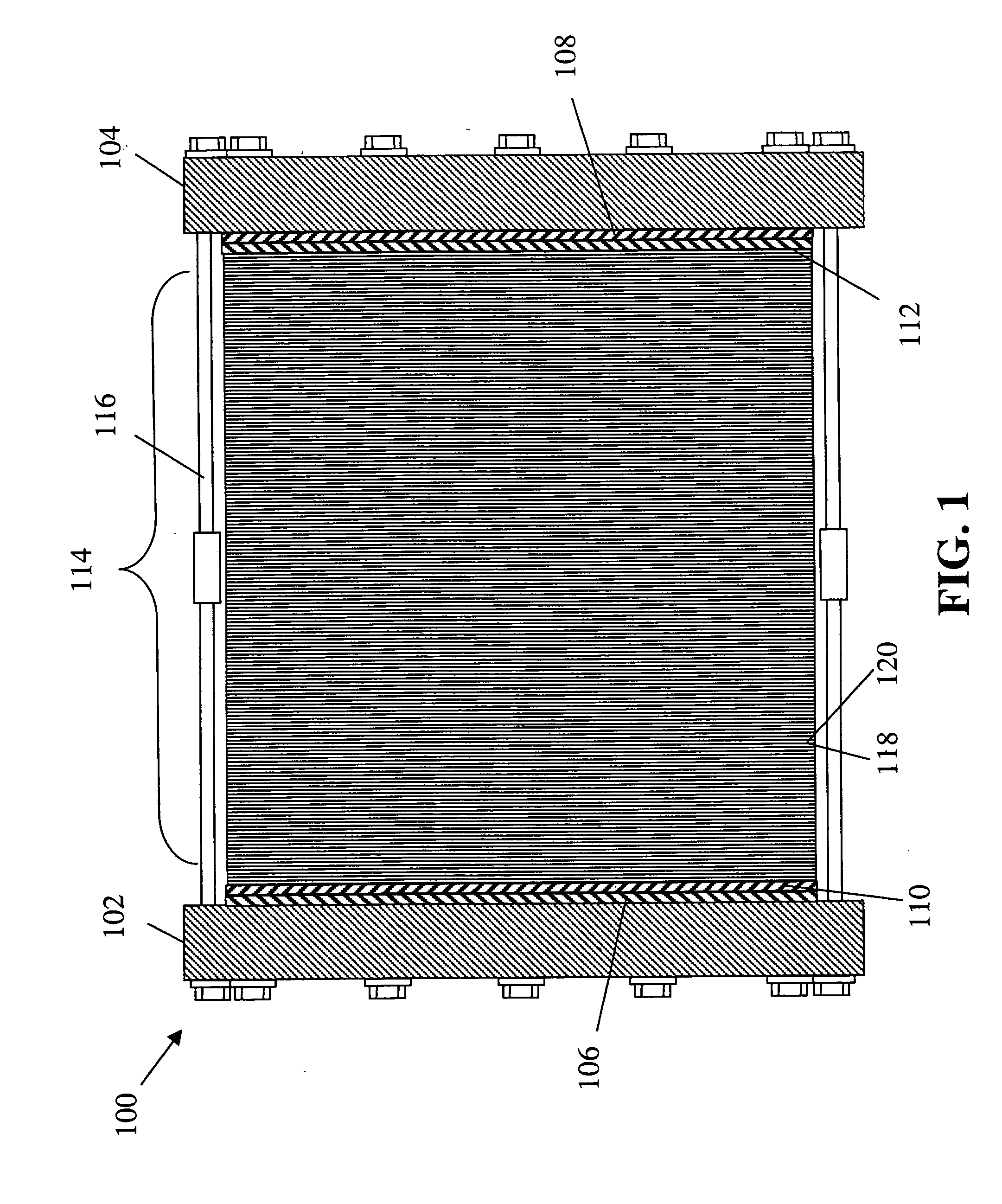
An example of a fuel cell assembly incorporating and using the novel features of the present invention is depicted in FIGS. 1-8 and described in detail herein.

As used herein, “predominately straight” means substantial parallel channels that run from inlet to outlet in a non-serpentine pattern. As used herein, “diffusion medium” means a layer in an electrochemical cell adjacent to the active catalytic sites which allows transport of reactant and product mass and electric current to and from the active sites, which is preferably a porous electrically conductive material. As used herein, “flow field plate” refers to a component of an electrochemical cell allowing ingress and egress of fluids such as reactant and waste gasses and liquids to and from reaction zones.

In a first exemplary embodiment shown by FIG. 1, a fuel cell assembly 100 includes end plates 102 and 104, insulation layers 106 and 108, and current collector / conductor plates 110 and 112, with a working section 114 ther...


PUM

PropertyMeasurementUnit
angleaaaaaaaaaa
widthaaaaaaaaaa
thicknessaaaaaaaaaa

Abstract

A fuel cell comprising anode and cathode flow field plates having a multitude of flow channels separated by land features wherein the land features of the anode side are wider than the land features of the cathode side is disclosed. In fuel cells, the flow field plate arrangement of the present invention provides higher power (lower cost per kW), improved durability, and less stringent assembly alignment.

Description

BACKGROUND OF THE INVENTION This invention relates generally to the field of electrochemical cells, and in particular to flow field plate arrangements for membrane electrode assemblies in fuel cells. Fuel cells are electrochemical devices which directly combine hydrogen from a fuel and oxygen, usually from the air, to produce electricity and water. With prior processing, a wide range of fuels, including hydrogen, natural gas, methanol, gasoline and coal-derived synthetic fuels, can be converted to electric power. Fuel cells may be used as stationary electric power plants in buildings and residences, as vehicle power sources in cars, buses and trucks and as portable power in video cameras, computers and the like. The basic process is highly efficient (40-75%), pollution-free, quiet, free from moving parts (other than an air compressor, cooling fans, pumps and actuators) and may be constructed to leave only heat and water as by-products. Since single fuel cells can be assembled into...

Claims


Application Information

Patent Timeline
Patent Type & Authority Applications(United States)
IPC IPC(8): H01M8/02H01M50/77
CPCH01M8/026Y02E60/50H01M8/0263
Inventor GOEBEL, STEVEN G.MILLER, DANIELBEUTEL, MATTHEW J.
Owner GM GLOBAL TECH OPERATIONS LLC
Why Eureka
Try Eureka