Self-Aligning Roofing Shingles

a technology of roofing shingles and self-aligning, which is applied in the field of roofing shingles, can solve the problems of saving installation tim

Inactive Publication Date: 2006-11-30
GEARY DAVID A
View PDF23 Cites 20 Cited by
  • Summary
  • Abstract
  • Description
  • Claims
  • Application Information

AI Technical Summary

Benefits of technology

[0005] It is therefore and object of this invention to provide a roofing shingle that is self-aligning with shingles located above it in an adjacent course, so that there is no need to manually align the shingles in order to properly shingle a roof.

Problems solved by technology

The result is that the shingles are easier to install, which saves installation time.

Method used


Image

  • Self-Aligning Roofing Shingles
  • Self-Aligning Roofing Shingles
  • Self-Aligning Roofing Shingles

Examples


Embodiment Construction

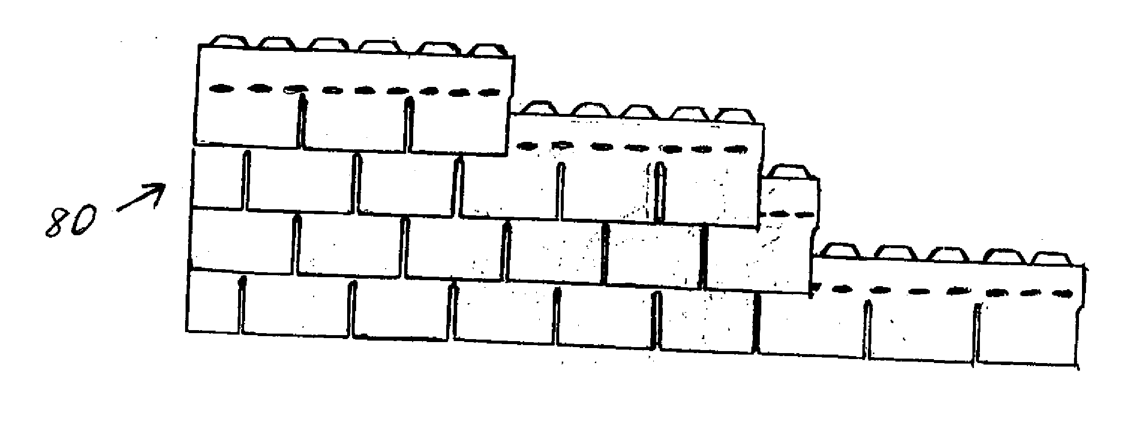
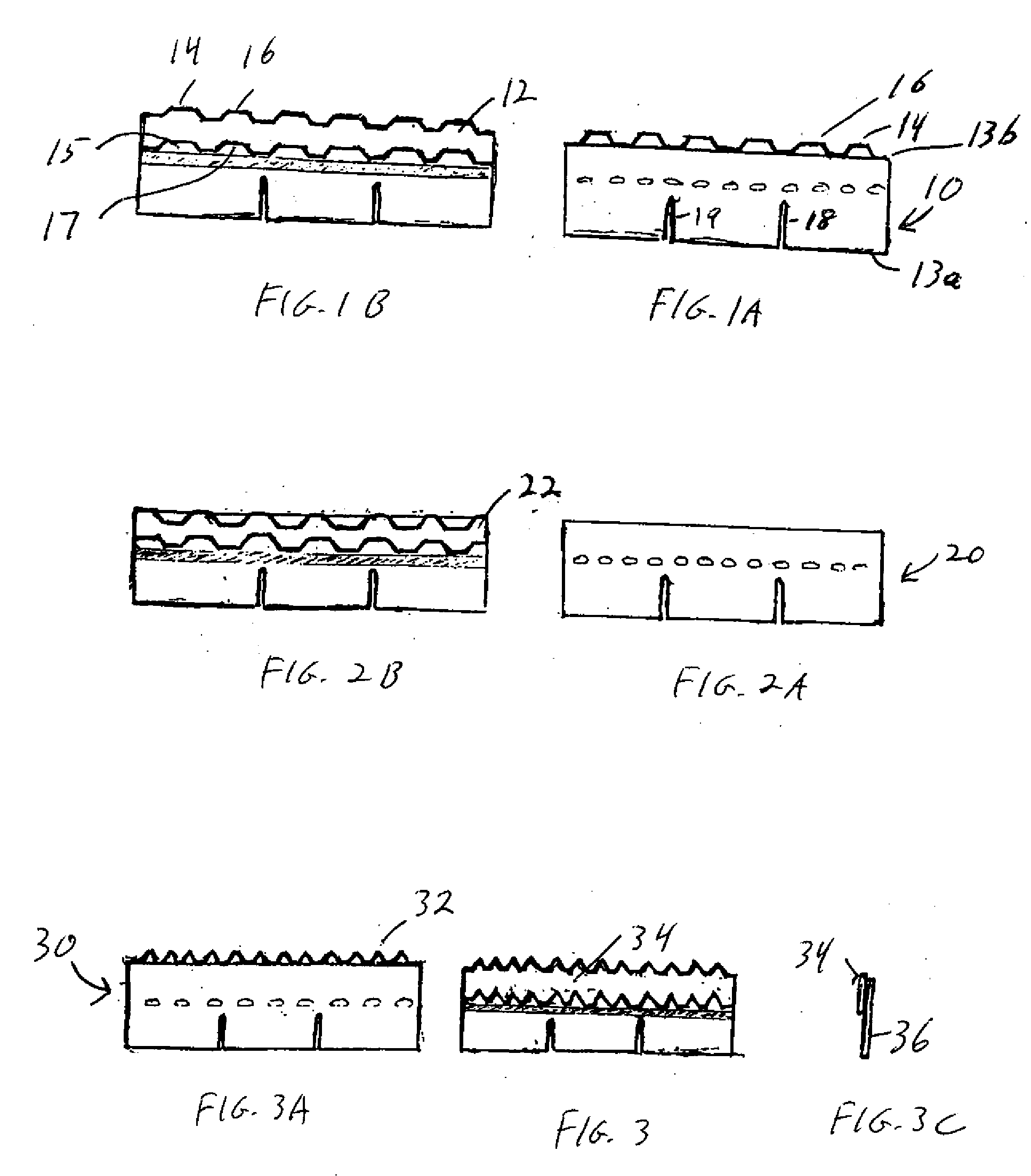
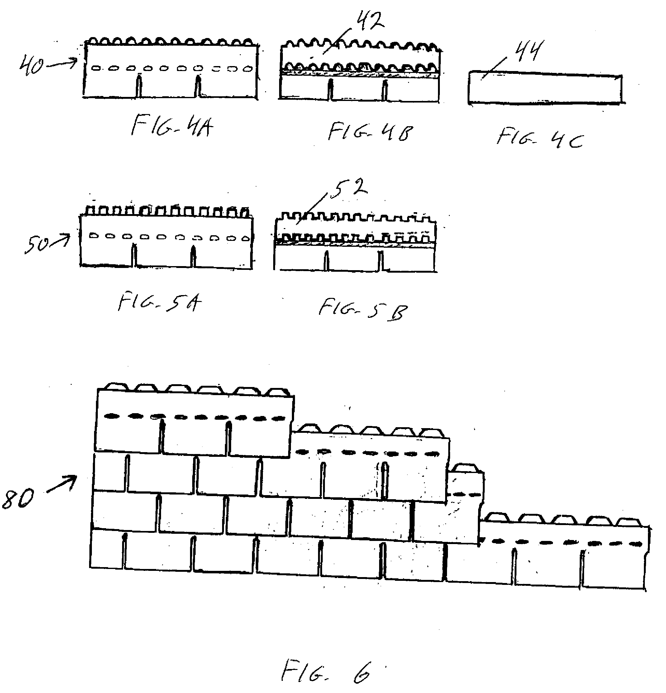
[0017] The invention is shown conceptually in FIGS. 1A and 1B, in which shingle 10 is a typical 3-tab shingle with slots 18 and 19 in the lower half of the shingle. Typical asphalt shingles have parallel bottom edge 13a and top edge 13b. In the invention, a locating strip 12 is added to the back of the shingle proximate upper edge 13b. Strip 12 has a series of regularly-spaced projections 14 and 16 and mating indentations 15 and 17. In this embodiment, strip 12 is formed with a regular series of projections along the top and matching indentations along the bottom. This can be created by forming, such as by die cutting, a strip of asphalt shingle material to create the serpentine shape. The strip is then attached to the back of the shingle with adhesive. Alternative manufacturing options such as directly forming the shingle with the locating features therein are possible. However, another advantage of the added strip design is that, as shown in the side view of FIG. 3C, the additiona...


PUM


Abstract

A self-aligning roofing shingle with a shingle body defining a top edge, and at least two spaced locating features proximate the top edge of the shingle body, each locating feature defined by a projection and an indentation, wherein a projection of one shingle in a first course of shingle locates in an indentation of a mating shingle in an adjacent course of shingles.

Description

CROSS REFERENCE TO RELATED APPLICATION [0001] This application claims priority of Provisional application Ser. No. 60 / 684,090 filed on May 24, 2005.FIELD OF THE INVENTION [0002] This invention relates to roofing shingles. BACKGROUND OF THE INVENTION [0003] Traditional asphalt roofing shingles are rectangular and have two spaced slots along their bottom edge. The shingles are laid such that the slots of shingles in adjacent courses are fully offset. [0004] In order to properly install shingles, each course musty be plumb and parallel to the adjacent courses. Doing so requires some degree of skill, which makes shingles relatively difficult and expensive to install. SUMMARY OF THE INVENTION [0005] It is therefore and object of this invention to provide a roofing shingle that is self-aligning with shingles located above it in an adjacent course, so that there is no need to manually align the shingles in order to properly shingle a roof. [0006] This invention comprises an asphalt-style r...

Claims


Application Information

Patent Timeline
Patent Type & Authority Applications(United States)
IPC IPC(8): E04D1/00
CPCE04D1/26
Inventor GEARY, DAVID A.
Owner GEARY DAVID A
Why Eureka
Try Eureka