
Method for compensating for a zero-point error in a vibratory gyroscope

Active Publication Date: 2006-11-30
LITEF
View PDF2 Cites 3 Cited by
  • Summary
  • Abstract
  • Description
  • Claims
  • Application Information

AI Technical Summary

Benefits of technology

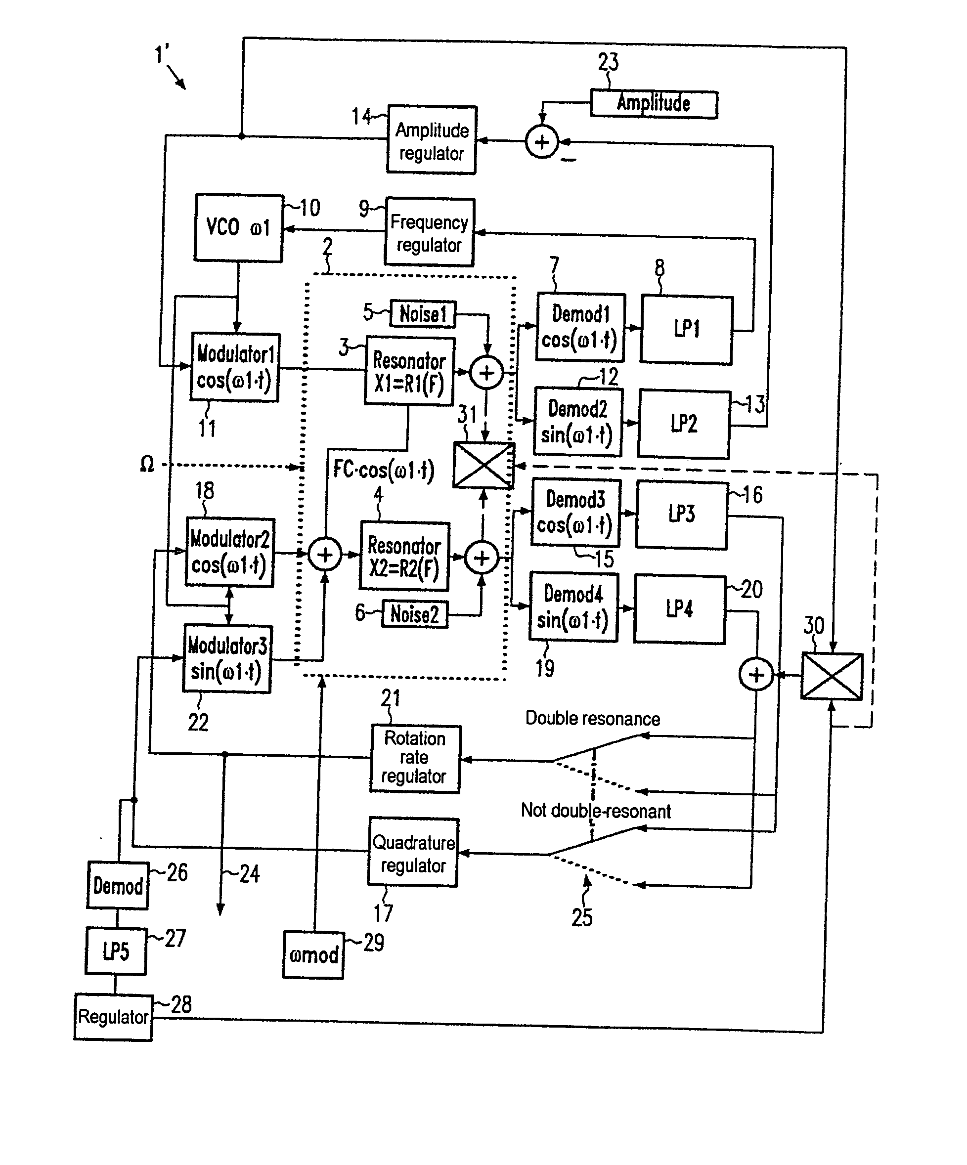
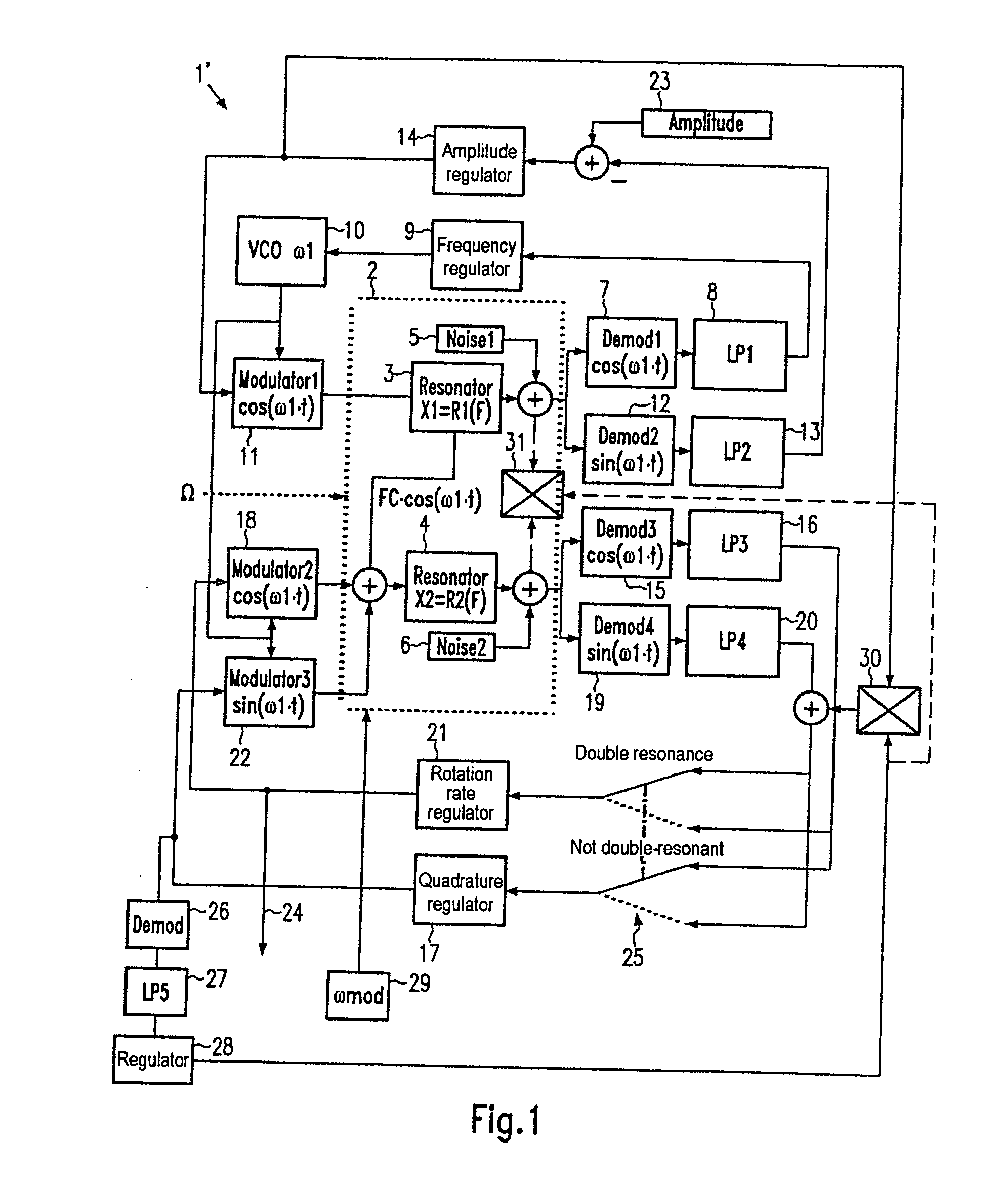
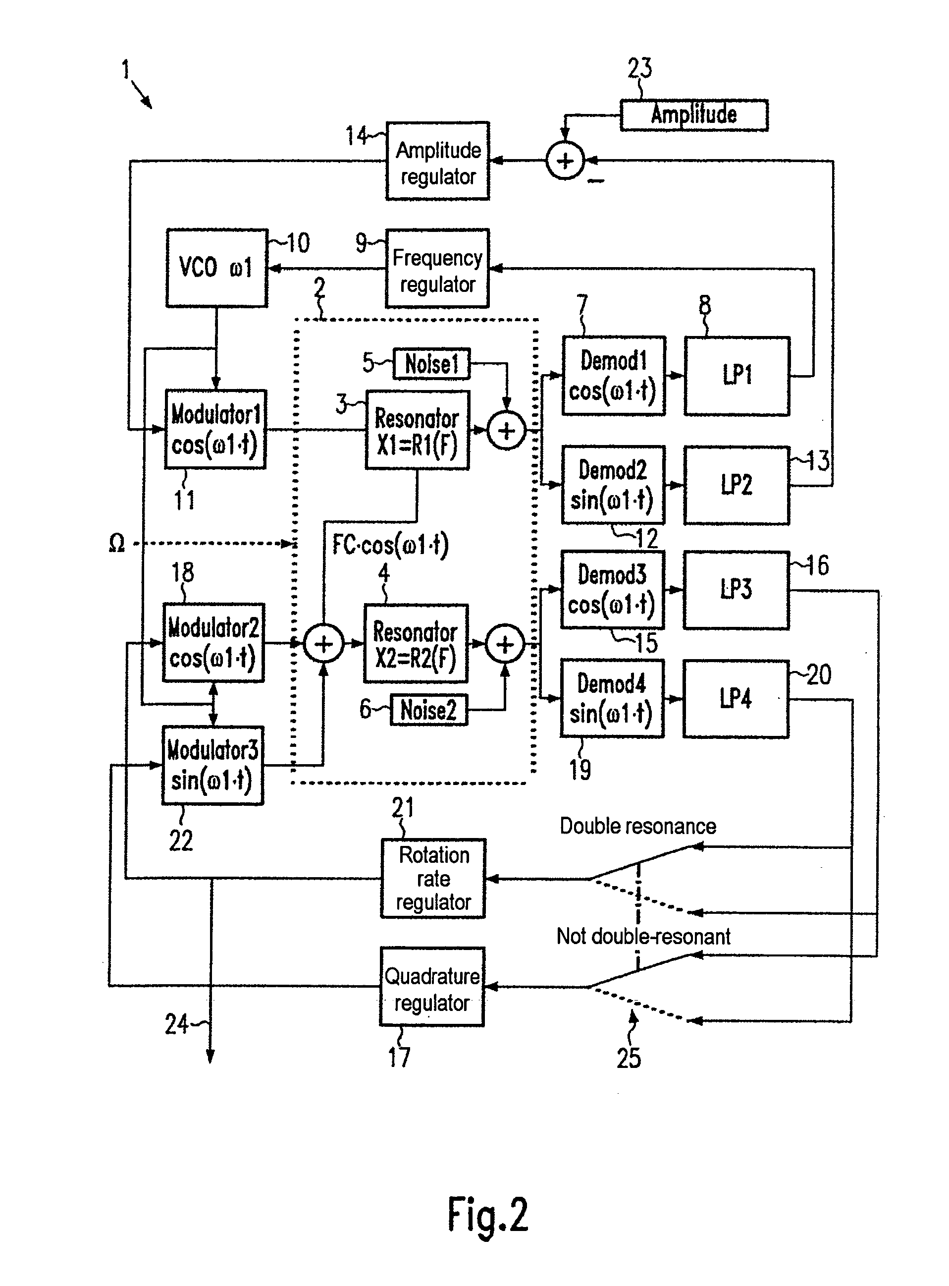
[0018] The present invention provides, in a first aspect, a method for compensation for a zero error in a Coriolis gyro. In such method, the frequency of the read oscillation is modulated. The output signal from a rotation rate control loop or quadrature control loop for the Coriolis gyro is demodulated in synchronism with the modulation of the frequency of the read oscillation to obtain an auxiliary signal which is a measure of the zero error. A compensation signal is then produced and passed to the input of the rotation rate control loop or quadrature control loop. The compensation signal is controlled so that the magnitude of the auxiliary signal is as small as possible.
[0019] In a second as

Problems solved by technology

Such misalignments must be taken into account as the read oscillation tapped-off signal is otherwise subject to errors.
The undesired part causes a Coriolis gyro zero error of unknown magnitude as it is impossible to distinguish between these two parts when the read oscillation tapped-off signal is tapped off.

Method used


Image

  • Method for compensating for a zero-point error in a vibratory gyroscope
  • Method for compensating for a zero-point error in a vibratory gyroscope
  • Method for compensating for a zero-point error in a vibratory gyroscope

Examples


Embodiment Construction

[0028] The general method of operation of a Coriolis gyro is explained again with reference to the vector diagrams of FIGS. 3 to 5 (Gaussian number plane). The method of the invention functions only at essentially double resonance (on average). Drawings labeled “close to double resonance” illustrate the changed conditions when the situation of “close to double resonance” occurs as a result of modulation of the resonant frequency of the read oscillation.

[0029] The vector diagram of FIG. 3 illustrates a Coriolis gyro (system 40) comprising a resonator (not shown), a force sensor system 41 and a tapping system 42. Possible oscillations x (stimulation) and y (read) are also indicated. Such oscillations are coupled to one another by Coriolis forces in the event of rotation at right angle to the plane of the drawing. The x oscillation (complex; purely imaginary at resonance) is stimulated by an alternating force with the complex amplitude Fx (in this case only the real part of Fxr). The ...


PUM


Abstract

A method for compensation of the zero error of a Coriolis gyro. The frequency of the read oscillation is modulated. The output signal from a rotation rate control loop or quadrature control loop for the Coriolis gyro is demodulated in synchronism with the modulation of the frequency of the read oscillation to obtain an auxiliary signal. The auxiliary signal is a measure of the zero error. A compensation signal is produced and passed to the input of the rotation rate control loop or quadrature control loop, with the compensation signal being controlled such that the magnitude of the auxiliary signal is as small as possible

Description

BACKGROUND [0001] 1. Field of the Invention [0002] The present invention relates to a Coriolis gyros. More particularly, this invention pertains to a method for compensation for a zero error in a Coriolis gyro. [0003] 2. Description of the Prior Art [0004] Coriolis gyros (also referred to as “vibration gyros”) are in increasing use for navigation. They possess a mass system that is caused to oscillate with the oscillation generally being the superposition of a large number of individual oscillations. [0005] The individual oscillations of the mass system are initially independent of one another and can be referred to abstractly as “resonators”. At least two resonators are required for operation of a vibration gyro: one (the first resonator) is artificially stimulated to oscillate, and this is referred to below as the “stimulating oscillation”. The other (the second resonator) is stimulated to oscillate only when the vibration gyro is moved / rotated. This is because Coriolis forces occ...

Claims


Application Information

Patent Timeline
IPC IPC(8): G01F25/00G01CG01C19/56
CPCG01C19/56
Inventor SCHROEDER, WERNER
Owner LITEF
Learn More