Active roll stabilizer

Active Publication Date: 2018-09-27
HL MANDO CORP
View PDF10 Cites 2 Cited by
  • Summary
  • Abstract
  • Description
  • Claims
  • Application Information

AI Technical Summary

Benefits of technology

[0020]In accordance with the embodiments of the present invention, since a torque measurement sensing part is mounted inside a carrier such that the active roll stabilizer can measure a torque without slippage generated at a coupler and nonlinearity of a damper.
[0021]In accordance with the embodiments of the present invention, the active roll stabilizer can be installed using a separate bolt and the like since a small torque measurement sensing part is mounted inside the carrier and thus a magnitude of an actually applied torque becomes very small.
[0022]In accordance with the embodiments of the present invention, the torque measurement sensing part is press-inserted into the carrier to accurately measure the torques generated at the pair of stabilizer bars such that the active roll stabilizer can prevent a rotation over a predetermined rotational angle and achieve stability of the vehicle by controlling a roll moment in a turning s

Problems solved by technology

Conventionally, the torque generated at the stabilizer bar may be measured using other torque sensors in addition to a strain gauge, but the other torque sensors are expensive, have a large size, and are not easy to install such that the torque is not easily measured.
Further, when the torque is measured using the strain gauge, an output value of the torque is varied according to a method of mounting the strain gauge and a mounting environment such that the torque may not be accurately measured, and since the strain gauge is mounted in a state of being exposed to the outside, durability of the strain gauge is degraded.
Meanwhile, in a structure for measuring the torque

Method used


Image

  • Active roll stabilizer
  • Active roll stabilizer
  • Active roll stabilizer

Examples


Example

[0031]Hereinafter, embodiments of the present invention will be fully described in detail which is suitable for easy implementation by those skilled in the art with reference to the accompanying drawings. The present invention may be implemented in various different forms, and thus it is not limited to the embodiments to be described herein. In the drawings, some portions not related to the description will be omitted and not be shown in order to clearly describe the present invention, and the same reference numerals are given to the same or similar components throughout the present invention.

[0032]It should be understood that the terms of “include” and “have” specify the presence of stated herein features, numbers, steps, operations, components, elements, or a combination thereof, but do not preclude the presence or probability of addition of one or more another features, numbers, steps, operations, components, elements, or a combination thereof.

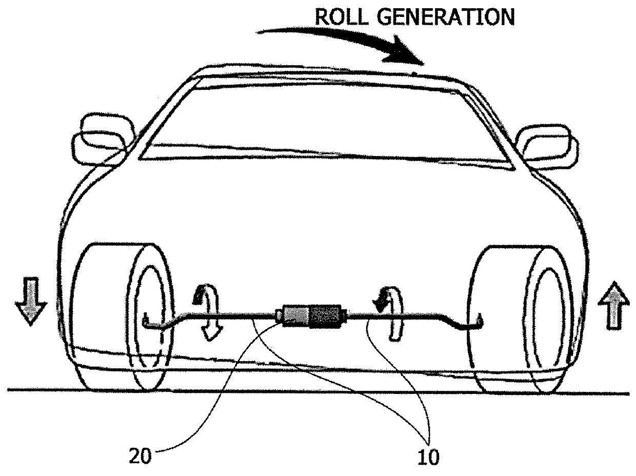
[0033]FIG. 1 is a schematic diagram ...


PUM


Abstract

Disclosed herein is an active roll stabilizer. The active roll stabilizer includes a pair of stabilizer bars installed between left and right wheels of a vehicle and an actuator which connects the pair of stabilizer bars and transmits a rotational force to the pair of stabilizer bars, wherein the actuator includes a motor configured to generate the rotational force, a housing coupled to a portion between the pair of stabilizer bars and having the motor disposed inside the housing, a damping part disposed on an extension line of a rotational shaft of the motor inside the housing and configured to absorb vibrations generated at the motor and the pair of stabilizer bars, and a torque measurement sensing part configured to measure a torque transmitted by the rotational force inside the damping part.

Description

CROSS-REFERENCE TO RELATED APPLICATION[0001]This application claims priority to and the benefit of Korean Patent Application No. 10-2017-0038241, filed on Mar. 27, 2017, the disclosure of which is incorporated herein by reference in its entirety.BACKGROUND1. Field of the Invention[0002]The present invention relates to an active roll stabilizer.2. Discussion of Related Art[0003]An active roll stabilizer mounted on a vehicle is configured to control a roll moment of the vehicle and prevents a pull phenomenon generated by a centrifugal force while the vehicle is turning left or right or is traveling on a rough road surface, thereby enhancing driving stability of the vehicle and improving ride comfort of a driver when the driver is driving the vehicle.[0004]The active roll stabilizer measures a torque of a stabilizer bar connected to wheels to control the roll moment.[0005]Conventionally, the torque generated at the stabilizer bar may be measured using other torque sensors in addition t...

Claims


Application Information

Patent Timeline
IPC IPC(8): B60G21/055
CPCB60G2800/012B60G2202/1351B60G21/0555B60G2600/21B60G2204/62B60G2800/9122B60G2400/98B60G2202/42B60G21/0553G01L5/22B60G2400/32B60G17/0157B60G2206/427B60Y2400/307
Inventor SIM, GYUNG HUN
Owner HL MANDO CORP
Why Eureka
Try Eureka