Direct drive electromechanical linear actuators

a linear actuator, direct drive technology, applied in mechanical equipment, gearing, hoisting equipment, etc., can solve problems such as backlash, wear, complexity and cost, and life limitations

Inactive Publication Date: 2006-11-30
THE BOEING CO
View PDF11 Cites 75 Cited by
  • Summary
  • Abstract
  • Description
  • Claims
  • Application Information

AI Technical Summary

Benefits of technology

[0017] In an alternative embodiment, the rollers can be located in adjacent planes perpendicular to the spindle, each plane containing a radially symmetrical array of two or more rollers. In another advantageous variation, the wall of the drum can be strained from a cylindrical shape to a trochoidal shape incorporating a plurality of longitudinal zones having a sm

Problems solved by technology

These problems include backlash, wear, c

Method used


Image

  • Direct drive electromechanical linear actuators
  • Direct drive electromechanical linear actuators
  • Direct drive electromechanical linear actuators

Examples


first exemplary embodiment

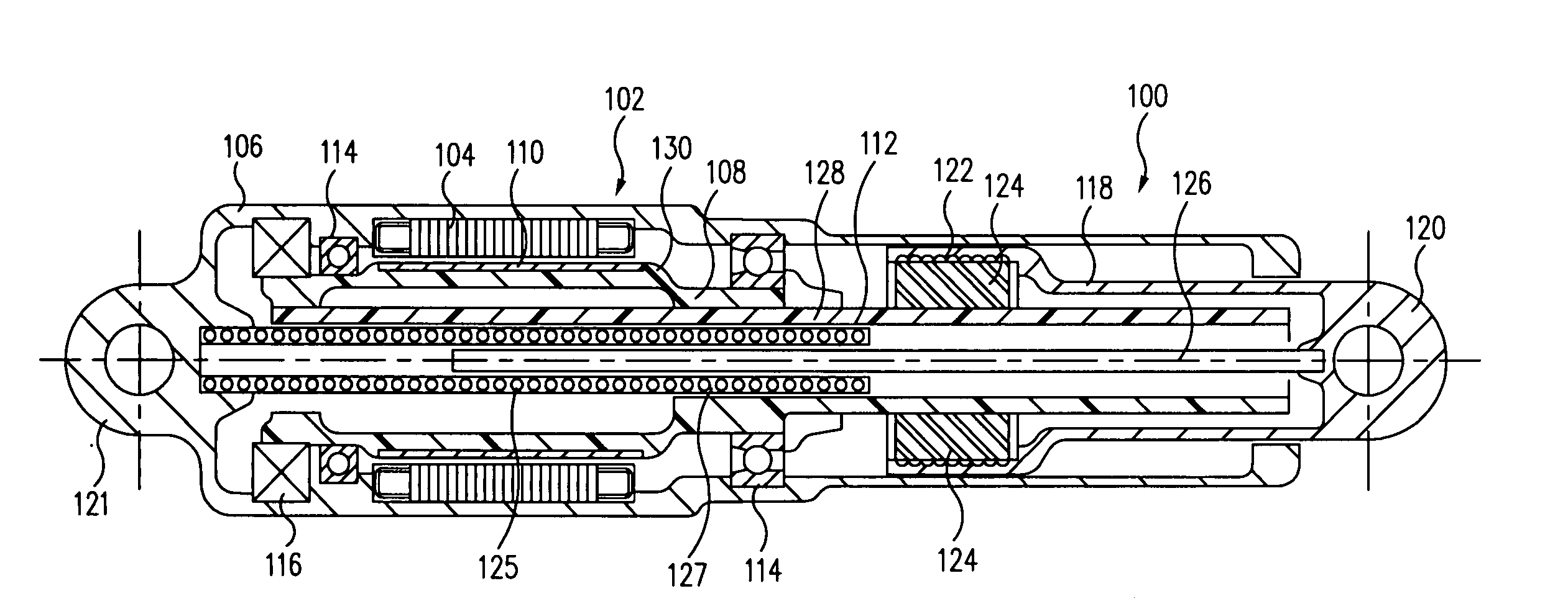
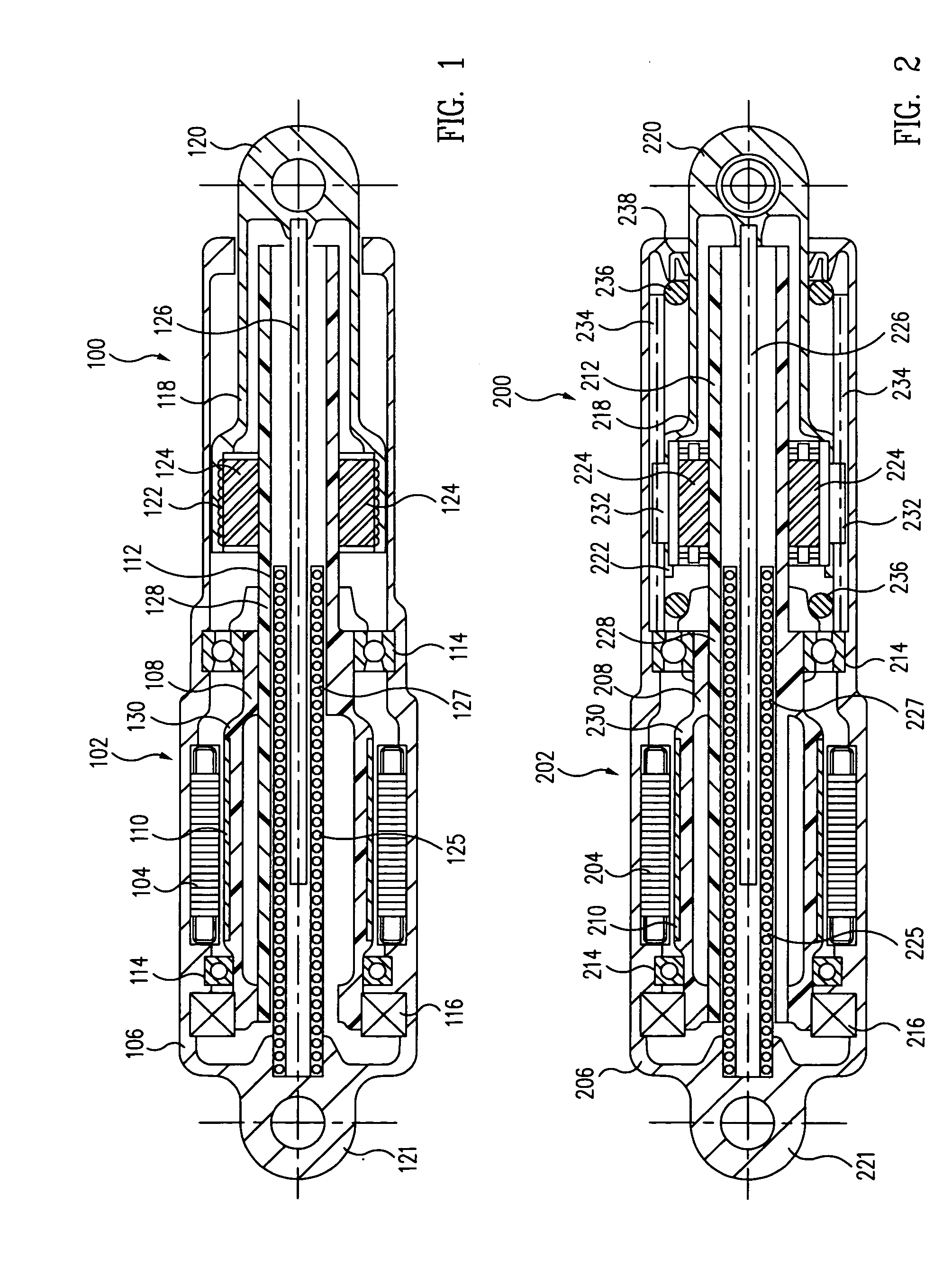
[0030] Turning now to the figures, a first exemplary embodiment of a direct drive electromechanical linear actuator 100 in accordance with the present invention, comprising a single motor, single-ended device, is illustrated in the cross-sectional side elevation view of FIG. 1. The actuator 100 comprises a brushless electric motor 102 having a stator 104 mounted in an elongated housing 106. A rotor 108 incorporating permanent magnets 110 and an elongated, externally threaded central shaft, or lead screw 112, is rotatably supported in the housing by a set of bearings 114. The rotor 108 supports a motor encoder 116 of a known type, which functions as a substitute for a motor commutator, for conjoint rotation with the rotor. A tubular output extension 118 having an output end 120, and containing an internally threaded planetary roller nut 122 located at the opposite end thereof, is disposed coaxially within and guided by the housing for both rotation about and translation along the lon...

second exemplary embodiment

[0033] A second exemplary embodiment of a direct drive electromechanical linear actuator 200 in accordance with the present invention, comprising a single motor, single-ended device with internal torque reaction, is illustrated in the cross-sectional side elevation view of FIG. 2. As may be seen by a comparison of the respective first and second embodiments of FIGS. 1 and 2, the second embodiment of actuator 200 incorporates several of the features of the first embodiment of actuator 100, but with the addition of a nut-and-output-end anti-rotation feature 232 and 234, as illustrated in FIG. 2. In particular, in the second embodiment, low-friction (e.g., Teflon) splines, or sliders 232, are disposed on the planetary nut 222 to slide with a slight interference fit in complementary longitudinal grooves, or tracks 234, disposed in the housing 206. The motor 202, and hence, the torque on the nut 222, is thereby reacted directly back to the housing, in a manner that prevents any rotationa...

third exemplary embodiment

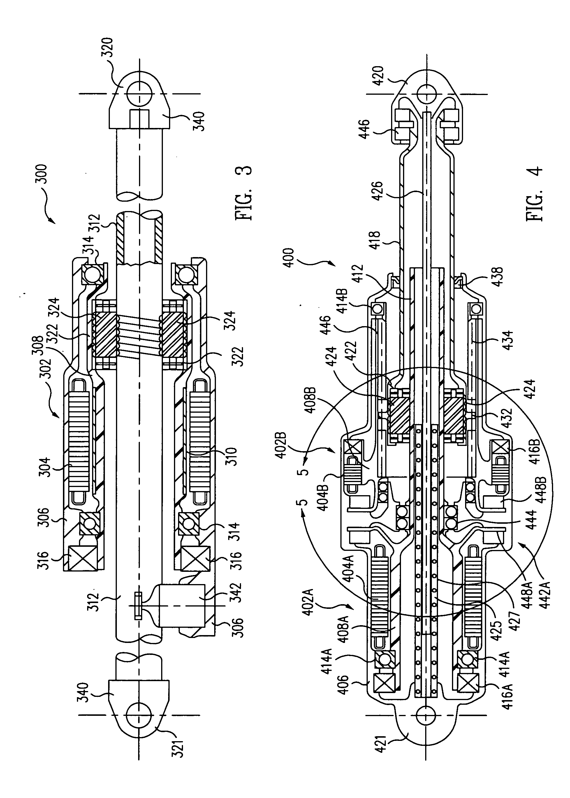
[0036] A third exemplary embodiment of a direct drive electromechanical linear actuator 300 in accordance with the present invention, comprising a single motor, and either a single- or double-ended device with enhanced travel range, is illustrated in the cross-sectional side elevation view of FIG. 3. As in the first and second embodiments above, a brushless electric motor 302 includes a stator portion 304 fixedly mounted in a housing 306. A rotor portion 308 is also rotatably supported in the housing by a set of bearings 314, and the rotor portion may also support a motor encoder 316 for conjoint rotation, as in the embodiments above.

[0037] As illustrated in FIG. 3, the rotor portion 308 of the motor 302 of the third embodiment is made as an elongated annular shaft on which neodymium-iron magnets 310 are mounted, as in the above embodiments, and in which the nut 322 of the planetary roller screw is concentrically mounted. The non-rotating central shaft, or lead screw 312, has a cle...


PUM


Abstract

Direct drive electromechanical rotary-to-linear actuators include one or more electric motors mounted in a housing. Each motor includes a stator and a rotor. The motor drives a planetary drive mechanism that includes an elongated central shaft having one or more helical threads on an external surface coupled to the rotor for conjoint rotation. A planetary nut having helical threads on an internal surface is disposed concentric to the shaft, and a plurality of planetary rollers are disposed concentrically between the shaft and the planetary nut. Each of the rollers has a helical thread on an external surface that is complementary to and in engagement with a thread of the shaft and a thread of the nut. Rotation of the rotor is converted with mechanical advantage into linear movement of the planetary nut. The actuators provide backlash-free operation, higher stiffnesses, slew rates and frequency responses, and better overall efficiency.

Description

TECHNICAL FIELD [0001] This invention relates to motion control or actuation devices in general, and in particular, to direct drive electromechanical rotary-to-linear motion actuators. BACKGROUND [0002] Electromechanical actuators are rapidly displacing hydraulic devices in a wide range of industries, including aviation. Improvements in solid state switching devices, their digital control and in the performance of magnetic materials have all contributed to an increased interest in electric actuators. Electromechanical linear actuators are particularly well suited to flight control applications, as well as a multitude of industrial uses, particularly in production automation. Automotive and other vehicle applications also abound, as may be found, for example, in the variable transmissions and caliper or disk brake actuators described in, e.g., U.S. Pat. Nos. 6,837,818 and 6,626,778 to Kapaan et al., and 6,367,597 and 6,318,512 to De Vries et al. [0003] Flight applications, such as ac...

Claims


Application Information

Patent Timeline
IPC IPC(8): F16H1/24
CPCF16H25/2252F16H2025/2075H02K7/06H02K7/102H02K11/0031Y10T74/18704H02K29/06Y10T74/19795Y10T74/186Y10T74/18624H02K16/00H02K11/225F16H2025/2081
Inventor WAIDE, WILLIAM M.
Owner THE BOEING CO
Why Eureka
Try Eureka