Self-locking inflation valve

Inactive Publication Date: 2006-11-30
CHEN CHIH MING
View PDF13 Cites 15 Cited by
  • Summary
  • Abstract
  • Description
  • Claims
  • Application Information

AI Technical Summary

Benefits of technology

[0010] 3. The arc of a resilient film bowl inserted to where between the valve plug and surface of the valve help ensure the positioning and airtight results of the valve plug while helping even more the fast airflow guide in air circulation.
[0011] 4. The self-locking mechanism will cause the extension tube of the aerator to be automatically ejected when the tube is rotated to be removed thus to synchronously shut off the valve and complete

Problems solved by technology

Furthermore, the absence of air from a power aerator in earlier time, the inflated object is vulnerable to air leakage and winding up in deflated condition.
With the introduction of the power aerator, the earlier form of inflated object that requires blowing air into it by mouth has already been gradually waived and is not applicable to the larger inflated object currently in fashion.
However, all currently inflated objects such as the inflated bed or inflated boat have relied on the one-way valve, meaning it takes strong air current to push opening the valve before in

Method used


Image

  • Self-locking inflation valve
  • Self-locking inflation valve
  • Self-locking inflation valve

Examples


Example

[0021] The following descriptions are of exemplary embodiments only, and are not intended to limit the scope, applicability or configuration of the invention in any way. Rather, the following description provides a convenient illustration for implementing exemplary embodiments of the invention. Various changes to the described embodiments may be made in the function and arrangement of the elements described without departing from the scope of the invention as set forth in the appended claims.

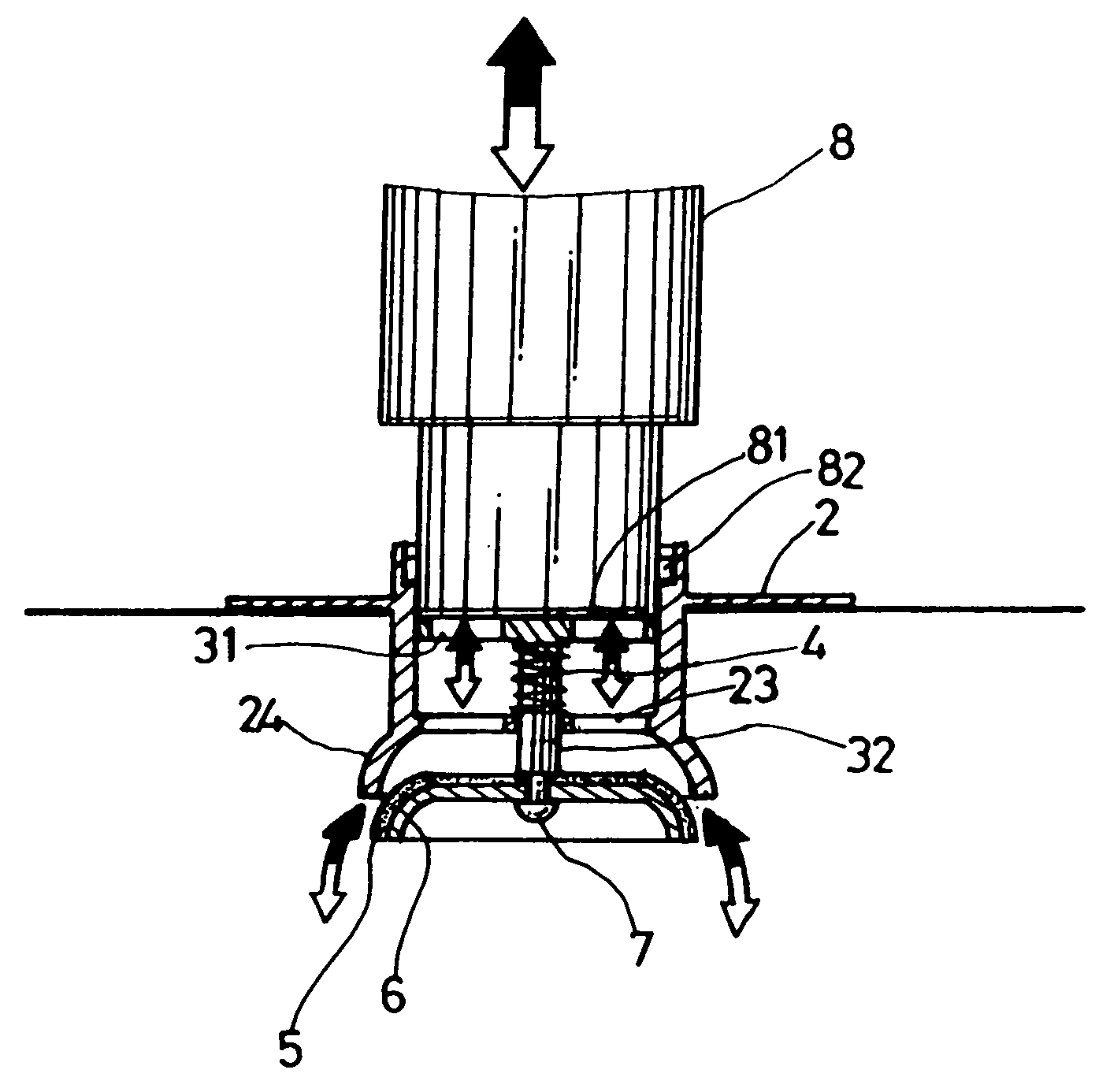
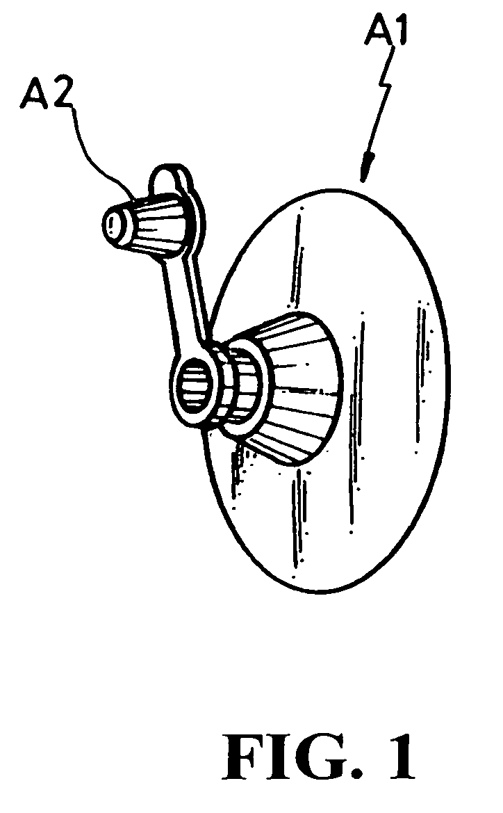
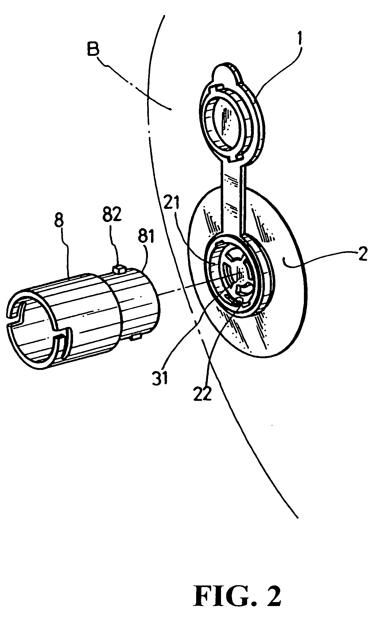
[0022] Referring to FIGS. 2 and 3, a valve of the present invention adapted to an inflated object (B) for inflation and deflation is essentially comprised of a foldable lid (1), a valve case (2), a displacement inner rod (3), a coil (4), a film bowl (5), a valve plug (6), and lock piece (7). Wherein, the lid (1) is inserted onto the outer circumference at the front of the valve case (2) to seal an inflation end (21) of the valve case (2); a locking slot (22) in symmetry and corresponding to the...


PUM


Abstract

A self-locking inflation valve works by having an extension inflation tube adapted to an aerator to execute locking in fashion of rotation and insertion to enable the inflation valve of the object to be inflated self-locking and secured type of opening for the object to achieve dual efficacies of inflation or air suction/drain; a mortise being provided in relation to the extension inflation tube on the inner edge of the end of an inflation valve assembly to enable self-locking when the tube being coupled into the mortise to force the inner valve to retreat thus to open up the inflation valve gate; and the inflation valve gate being automatically shut off through a built-in coil once the extension tube clears away from the mortise.

Description

BACKGROUND OF THE INVENTION [0001] (a) Technical Field of the Invention [0002] The present invention is related to a self-locking inflation valve, and more particularly, to a construction of an inflation valve with a breakthrough of utility. [0003] (b) Description of the Prior Art [0004] Inflation products generally available in the market are usually used in the fields of entertainment, sports and leisure activities with the primary appeal of having the inflated object to provide its specific style as desired without compromising its lightweight and agile operation features for use in water or on land. Therefore, the inflated object may be as small as in the form of a swimming ring or inflated toy or as big as an inflated bed, or inflated boat. An inflation valve is a must to any type of inflated object, and has significant affects upon the quality, service life, and use safety of the inflated object. [0005] As illustrated in FIG. 1 of the accompanying drawings for an inflation val...

Claims


Application Information

Patent Timeline
IPC IPC(8): F16K21/00
CPCF16K15/20Y10T137/3584
Inventor CHEN, CHIH-MING
Owner CHEN CHIH MING
Why Eureka
Try Eureka