Gain-flattening apparatus and methods and optical amplifiers employing same

a technology of gain-flattening apparatus and optical amplifier, which is applied in the direction of fiber transmission, lasers, transmission, etc., can solve the problems of theoretical transmission curve of gain, uneven gain level of commercially employed optical amplifier, and general undesirable

Active Publication Date: 2006-11-30
II VI DELAWARE INC
View PDF8 Cites 8 Cited by
  • Summary
  • Abstract
  • Description
  • Claims
  • Application Information

AI Technical Summary

Problems solved by technology

Commercially employed optical amplifiers typically provide an uneven level of gain across their optical wavelength range.
This is generally undesirable, as flat gain characteristics, i.e., level signal strength across the operating bandwidth of the system, typically are important in multiplexed optical systems for increased transmission distance, reduced signal-to-noise ratios and other non-linear effects, or to meet other operating requirements of the system.
Design limitations may result in the theoretical transmission curve of the gain-flattening differing somewhat from the target curve.
The error functions of gain-flattening filters and other gain-flattening devices are somewhat dependent on the desired attenuation profile, and thin-film gain-flattening devices such as filters show larger error functions as the attenuation profile or modulation depth becomes larger or more complex.
In this regard it is a problem that if multiple thin-film gain-flattening filters are used in series, such as suggested by Hwang et al. cited above, for example, two thin-film gain-flattening filters each correcting 6 dB of modulation depth for a total gain compensation of 12 dB, the error function and PPEF tend to accumulate.
The error function tends to accumulate because thin-film gain-flattening filters typically have systematic error functions.
Consequently, cascading gain-flattening filters having such systematic errors, either by packaging multiple filters into a common housing or positioning multiple discrete gain-flattening filters in series along an optical fiber path, will cause an accumulation of error.
Similar error function concerns are raised with other gain-flattening devices.
The first filter does not perfectly flatten the amplifier's gain profile and rather has a net insertion loss error function relative to the spectral gain profile of the associated optical amplifier for optical signals in the optical wavelength range.

Method used


Image

  • Gain-flattening apparatus and methods and optical amplifiers employing same
  • Gain-flattening apparatus and methods and optical amplifiers employing same
  • Gain-flattening apparatus and methods and optical amplifiers employing same

Examples


Embodiment Construction

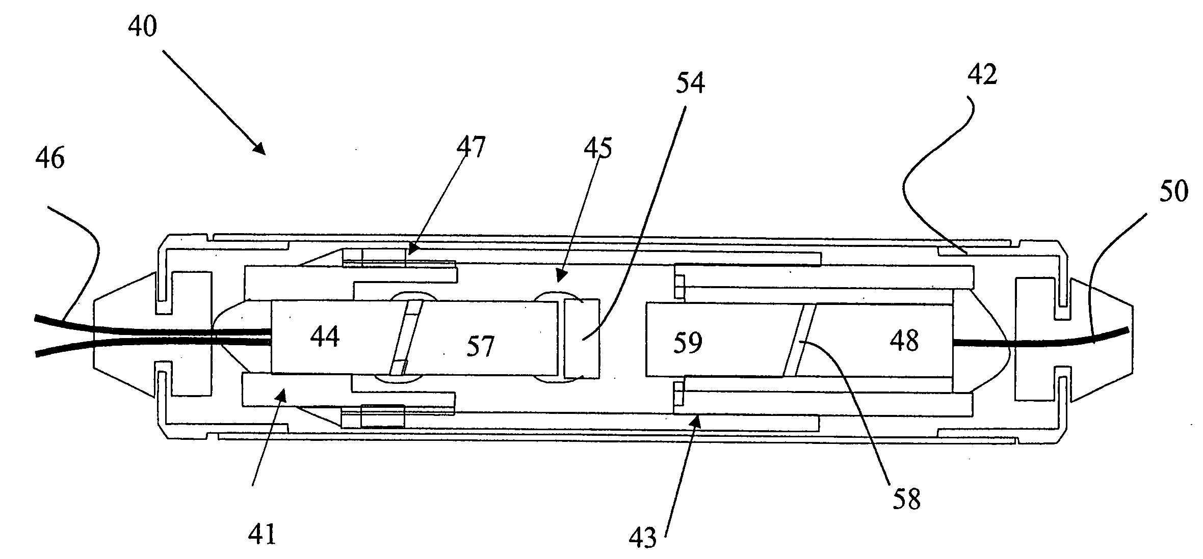
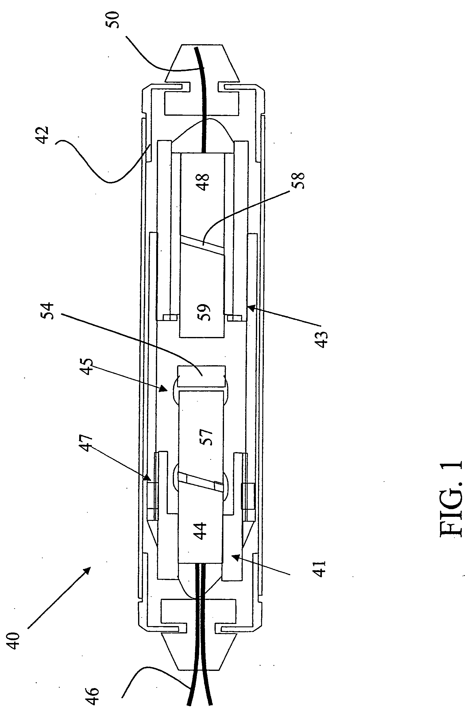
[0028] The following discussion of certain exemplary embodiments of the invention focuses on gain-flattening apparatus used in multiplexed optical signal systems, such as telecommunication systems and the like. GFF apparatus, gain-flattened optical amplifiers employing them, their design and production, and methods of the present invention, however, are applicable generally to optical systems. Reference is made here to commonly assigned U.S. patent application Ser. No. 10 / 874,559, entitled Gain-Flattening Apparatus And Methods And Optical Amplifiers Employing Same, published on Nov. 10, 2005 as U.S. patent application publication number 20050248832 A1, which is incorporated here by reference in its entirety for all purposes. In certain of the embodiments disclosed here, for convenience of discussion, the gain-flattening apparatus are designed for dense wavelength division multiplexed (“DWDM”) telecommunications systems operating in the C-band and employing EDFA amplifiers. However, ...


PUM


Abstract

Gain-flattening components for compensation of at least a portion of the spectral gain profile of an optical amplifier comprises an optical substrate having at least a first gain-flattening filter disposed on a first surface of the optical substrate and a second gain-flattening filter disposed on a second surface of the optical substrate. The first gain-flattening filter has a transmission curve with a spectral loss profile for optical signals in the optical wavelength range, and has a net insertion loss error function relative to the spectral gain profile of an optical amplifier. The spectral loss profile of the second gain-flattening filter corresponds to the net insertion error function of the first gain-flattening filter. Gain-flattening optical amplifiers comprise one or more such gain-flattening components and at least one optical signal amplifier. Methods of producing gain-flattening components comprise: designing a primary gain-flattening filter to flatten the spectral gain profile of an optical amplifier; disposing on a first surface of an optical substrate a first gain-flattening filter according to the design of the primary gain-flattening filter; determining the error function of the coated substrate; designing a tweaker filter with a spectral loss profile corresponding to the error function of the coated substrate; and disposing on the second surface of the optical substrate a second filter according to the design of the tweaker filter.

Description

INTRODUCTION [0001] The present invention relates to certain improved gain-flattening apparatus, including gain-flattening apparatus suitable for use in optical systems, such as telecommunication systems or other systems employing optical signals, and to improved methods of producing and using gain-flattening apparatus, and to gain-flattened amplifiers incorporating such gain-flattening apparatus. CROSS-REFERENCE [0002] This application claims the priority benefit of British Patent Application No. 0410233.1, filed May 10, 2004 and Utility patent application Ser. No. 10 / 874,559, filed Jun. 23, 2004, the disclosure of which is hereby expressly incorporated herein. BACKGROUND [0003] Optical signal systems wherein multiple signal channels are carried by optical fibers or other waveguides over extended distances are known to employ optical amplifiers to batch-amplify all of the signal channels simultaneously. Commercially employed optical amplifiers typically provide an uneven level of g...

Claims


Application Information

Patent Timeline
Patent Type & Authority Applications(United States)
IPC IPC(8): H01S3/00H04B10/12H04B10/17
CPCG02B5/28G02B6/2937G02B6/2938H04B10/2941H01S3/06754H01S3/10023H01S2301/04G02B6/29395G02B5/23
Inventor SOMMER, RADFORTENBERRY, RANCE M.
Owner II VI DELAWARE INC
Why Eureka
Try Eureka