Composite extensible member and method of manufacturing the same

a composite member and extensible technology, applied in the field of extensible composite member and a manufacturing method, can solve the problem of poor touch of folds, and achieve the effect of improving softness and skin feel

Active Publication Date: 2006-11-30
KAO CORP
View PDF3 Cites 116 Cited by
  • Summary
  • Abstract
  • Description
  • Claims
  • Application Information

AI Technical Summary

Benefits of technology

[0007] The elastically extensible portion described in reference-2 is not very soft in the direction parallel with the linear joints between the sheet material layers due to the joints and therefore leaves room for improvement in softness and feel to the skin.

Problems solved by technology

However, the feel to the touch of the folds is not so good on account of the joints between the sheet material and the elastic members.

Method used


Image

  • Composite extensible member and method of manufacturing the same
  • Composite extensible member and method of manufacturing the same
  • Composite extensible member and method of manufacturing the same

Examples


first embodiment

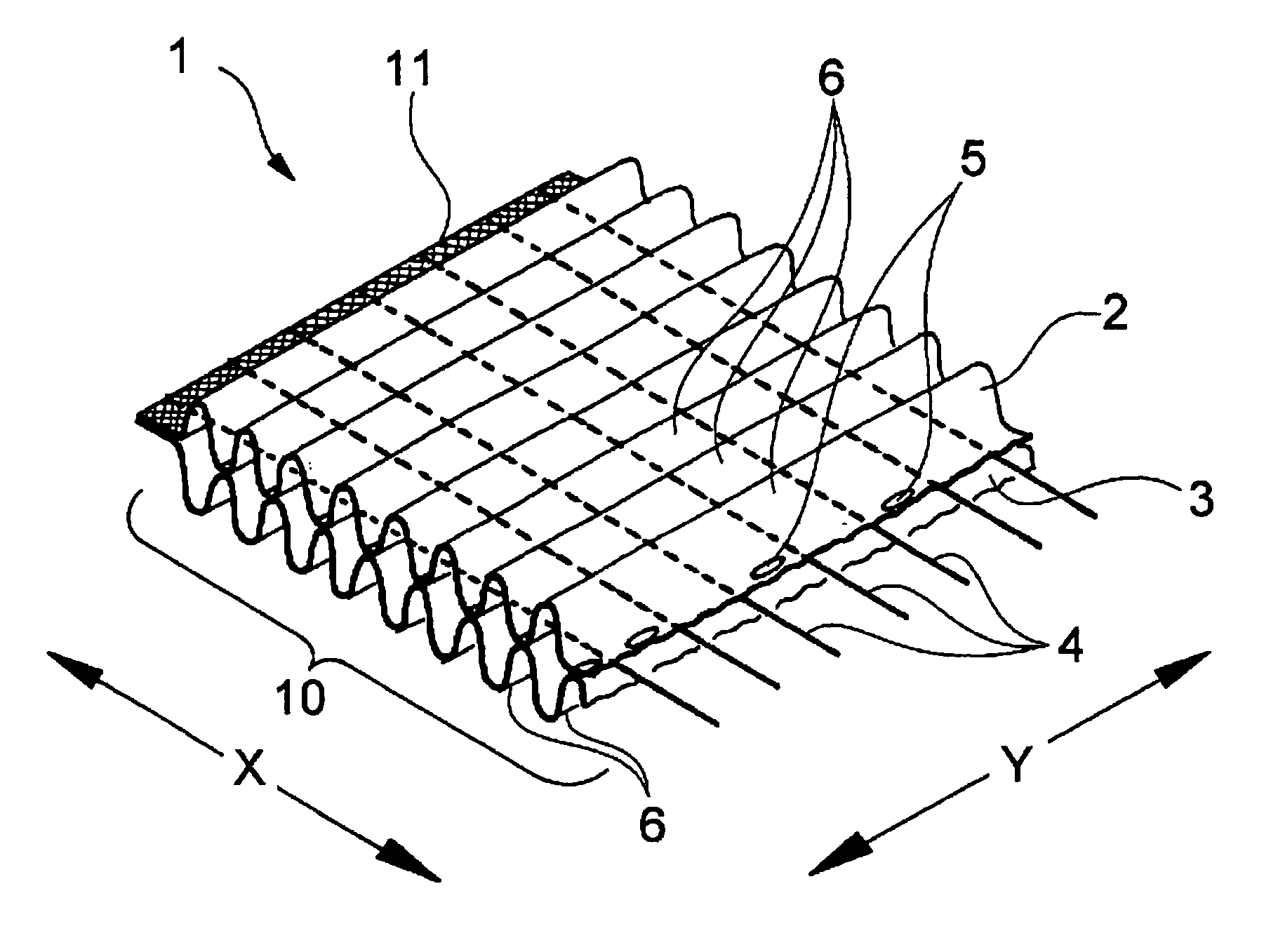
[0030] Preferred embodiments of the first and the second aspects of the present invention will be described with reference to the accompanying drawings. As illustrated in FIG. 1, an extensible composite member 1 according to an embodiment (first embodiment) of the first aspect of the present invention has an extensible portion composed of two sheet materials 2 and 3 and a plurality of elastic members 4 disposed between the two sheets.

[0031] The extensible portion 10 is formed in a central portion of the extensible composite member 1 in the elastic members 4 extending direction. The elastic members 4 are joined to the sheet materials at both end portions 11 (only one of the end portions is shown) of the extensible composite member 1 in that direction.

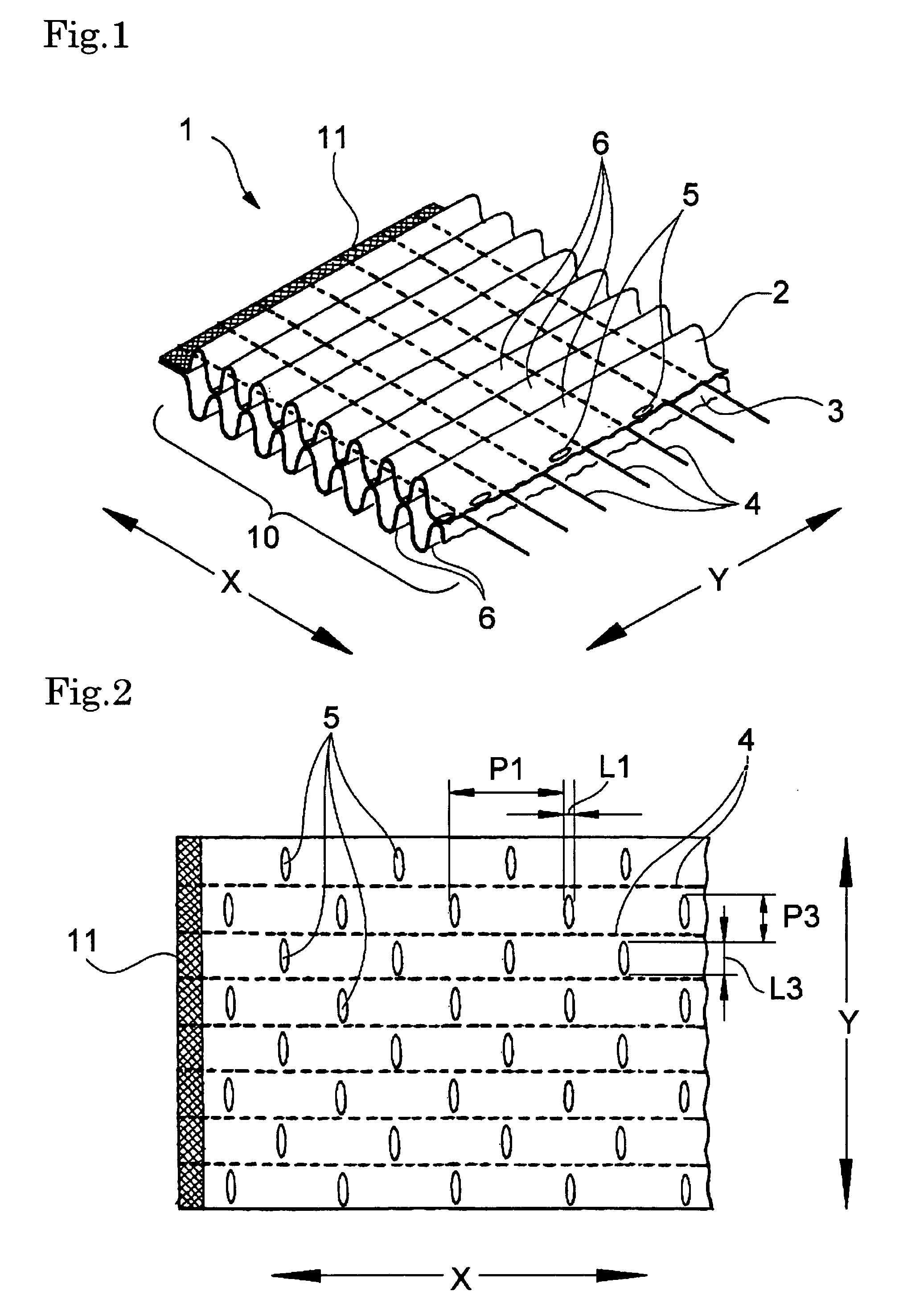
[0032] As illustrated in FIG. 2, the two sheet materials 2 and 3 composing the extensible portion 10 are fusion bonded joined) to each other discontinuously in both the extensible portion 10 extending direction (X direction) and a direc...

second embodiment

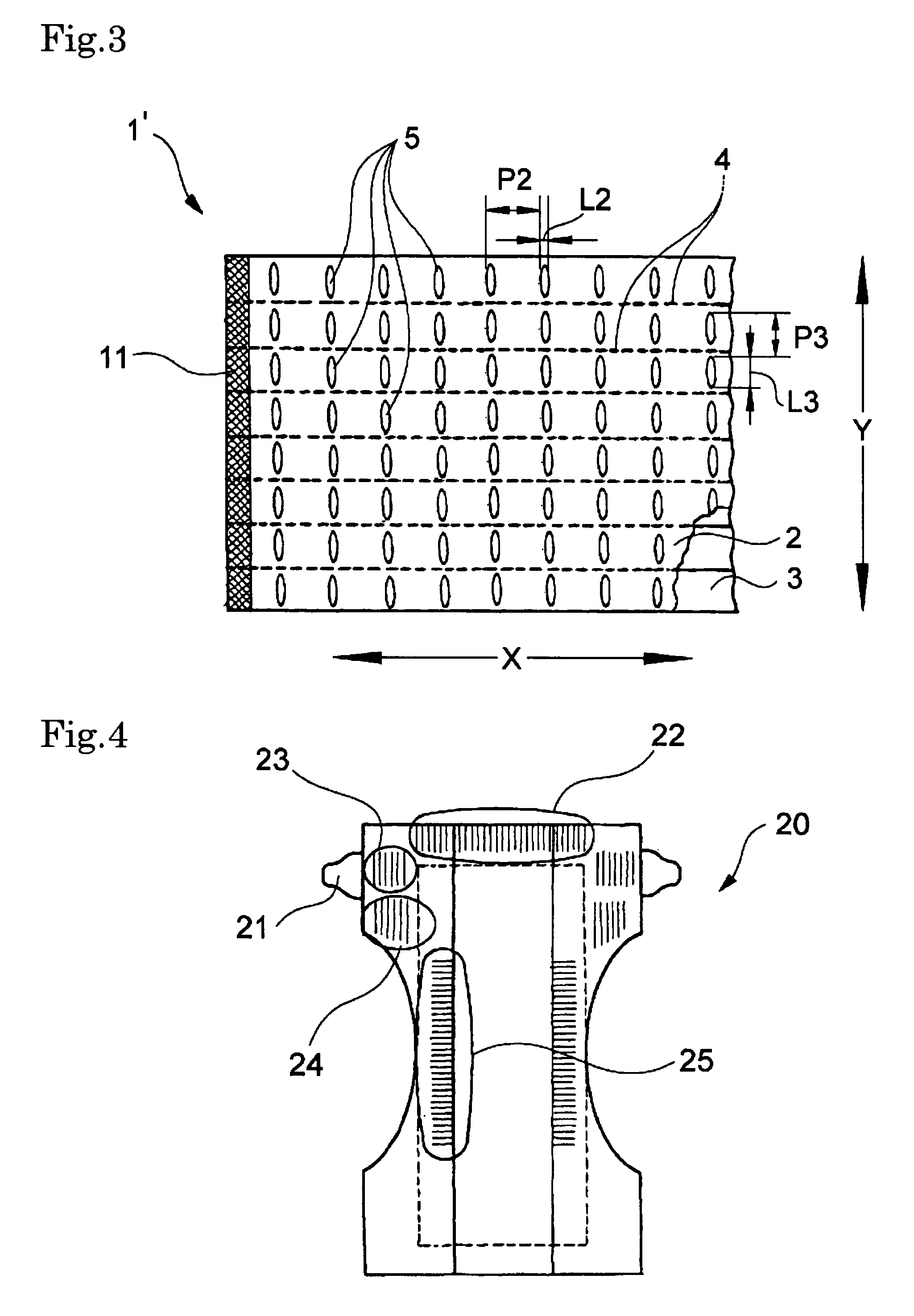
[0070] In the second embodiment, one fold 6 is created between every two fusion joints 5 that are adjacent in the extensible portion extending direction (X direction).

[0071] In order to assure formation of folds 6 continuously running across a plurality of the elastic members 4, it is preferred that the fusion joints 5 be arranged at a pitch P2 (see FIG. 3) of 1 to 20 mm, more preferably 3 to 10 mm, in the extensible portion 10 extending direction (X direction) with the extensible portion 10 being in the extended state; that the individual fusion joints 5 have a length L2 (see FIG. 3) of 0.1 to 5 mm, more preferably 0.2 to 1.5 mm in the same direction in the same state; and that the ratio of the pitch P2 to the length L2 (P2 / L2) be in the range of from 1.1 to 200, more preferably from 2 to 50.

[0072] In the above-illustrated extensible composite members 1 and 1′, especially the extensible composite member 1, it is preferred that the pitch P3 (see FIGS. 2 and 3) of the fusion joints ...


PUM

PropertyMeasurementUnit
length L1aaaaaaaaaa
length L1aaaaaaaaaa
length L2aaaaaaaaaa

Abstract

An extensible composite member (1) including an extensible portion (10) having two sheet materials (2, 3) and elastic members (4) intermediate between the sheet materials. The two sheet materials (2, 3) are discontinuously bonded to each other in the extending direction of the extensible portion (10) (X direction) and a direction perpendicular thereto (Y direction). The elastic members (4) are arranged in the extensible portion (10) avoiding joints (5) between the sheet materials and have both ends thereof fixed to the sheet materials. Each of the two sheet materials (2, 3) forms folds (6) continuously running across a plurality of the elastic members (4).

Description

TECHNICAL FIELD [0001] The present invention relates to an extensible composite member and a method of making the same. BACKGROUND ART [0002] In the field of absorbent articles including disposable diapers and sanitary napkins, it is a practice widely adopted to bond an elastic member in its stretched state to a sheet material and allow the elastic member to contract thereby to make gathers (an extensible portion with a large number of folds) of the sheet. [0003] JP-A-2001-11769 (reference-1) discloses an elastically extensible sheet having a flat sheet material accordion-folded to make a large number of folds and elastic members bonded to the top of a plurality of the folds. [0004] Japanese Utility Model 2518953 (reference-2) discloses a disposable diaper having an elastically extensible portion having a sheet material of nonwoven fabric folded back into two layers and an elastic member sandwiched between the two layers. The sheet material is joined to itself along linear joints ex...

Claims


Application Information

Patent Timeline
Patent Type & Authority Applications(United States)
IPC IPC(8): B32B3/28D04H13/00B32B5/26A61F13/15
CPCA61F13/4902Y10T428/24058B32B5/022B32B5/04B32B5/08B32B5/12B32B5/26B32B2250/20B32B2262/0207B32B2262/0253B32B2262/0292B32B2307/51B32B2307/538B32B2307/546B32B2307/724B32B2307/726B32B2555/02Y10T428/24686Y10T428/24041B32B3/28B32B27/283B32B27/365B29K2995/0046B29L2031/4878B29C65/087B29C65/18B29C66/1122B29C66/21B29C66/433B29C66/71B29C66/7294B29C66/81431B29C66/81433B29C66/83413B29C65/02Y10T442/60Y10T442/601Y10T442/602Y10T442/659B29K2023/06B29K2023/12B29K2023/00B29K2075/00B29K2009/06B29K2007/00B29K2023/083
Inventor ANDO, KENJIKOBAYASHI, KENJI
Owner KAO CORP
Why Eureka
Try Eureka