
Assisted systems and methods for performing transvaginal hysterectomies

a technology of assisted systems and methods, applied in the field of medical equipment and methods, can solve problems such as compromising ability and exposing patients to risk, and achieve the effect of facilitating the removal of the uterus

Inactive Publication Date: 2006-11-30
FORCEPT
View PDF99 Cites 75 Cited by
  • Summary
  • Abstract
  • Description
  • Claims
  • Application Information

AI Technical Summary

Benefits of technology

[0012] In some embodiments of the present invention, the cervix may be manually dissected and pulled in order to pass the uterus through the opposed cutting and cauterizing elements on the frame. In such cases, the use of an automatic traction device is not necessary. The opposed cutting and cauterizing elements will still provide facilitated cutting and cauterization the blood vessels, ligaments, and other tissue structures extending between the uterus and surrounding tissues. Additionally, the frame may provide rollers, optical elements, or other means for mechanically monitoring the rate and / or force of pulling in order to provide an alarm should the rate of extraction be excessive (thus compromising the ability of the frame to provide proper cauterization and hemostatis) or should the force of pulling be excessive, exposing the patient to risk.
[0015] The frame and / or the cutting and coagulation elements will typically be adjustably mounted to separate in order to accommodate the width of the uterus as it passes through the opening and frame. For example, the frame could define a split ring having halves which are biased closed and which will move apart as the uterus is drawn therethrough. In the later case, at least one cutting and coagulation element will typically be coupled to each half of the ring. The systems may further comprise a tissue dissection blade disposed across the frame opening, typically behind the coagulation and cutting elements so that the uterine body may be dissected after it has passed through the frame opening. Such dissection facilitates removal of the uterus. In still other embodiments, the electrodes may be cylinder culled and rotatively mounted on the frame.

Problems solved by technology

Additionally, the frame may provide rollers, optical elements, or other means for mechanically monitoring the rate and / or force of pulling in order to provide an alarm should the rate of extraction be excessive (thus compromising the ability of the frame to provide proper cauterization and hemostatis) or should the force of pulling be excessive, exposing the patient to risk.

Method used


Image

  • Assisted systems and methods for performing transvaginal hysterectomies
  • Assisted systems and methods for performing transvaginal hysterectomies
  • Assisted systems and methods for performing transvaginal hysterectomies

Examples


Embodiment Construction

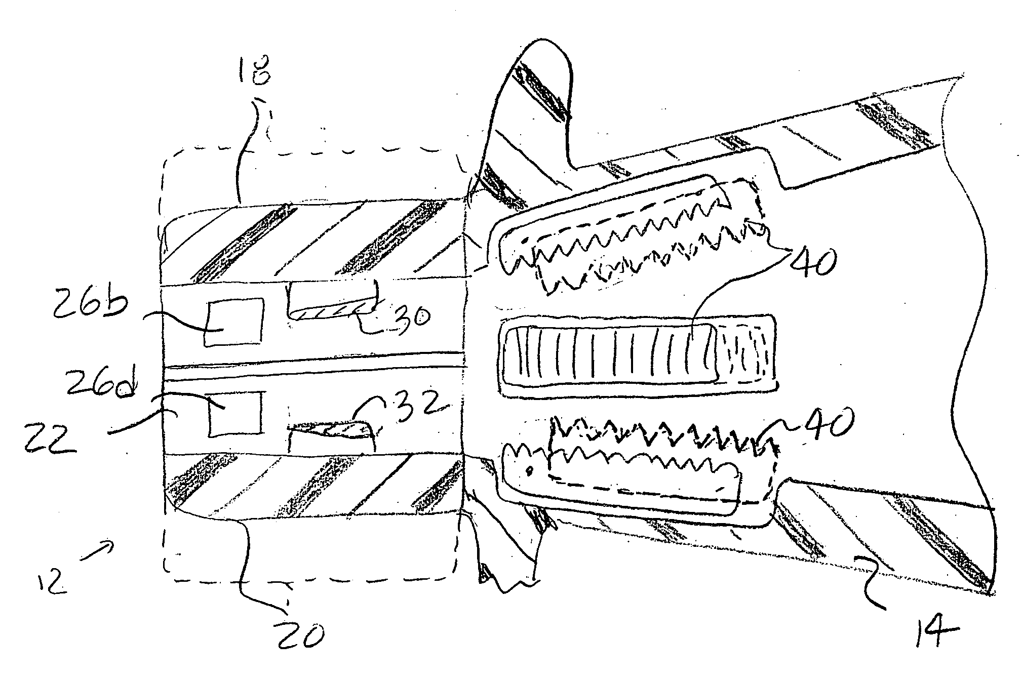
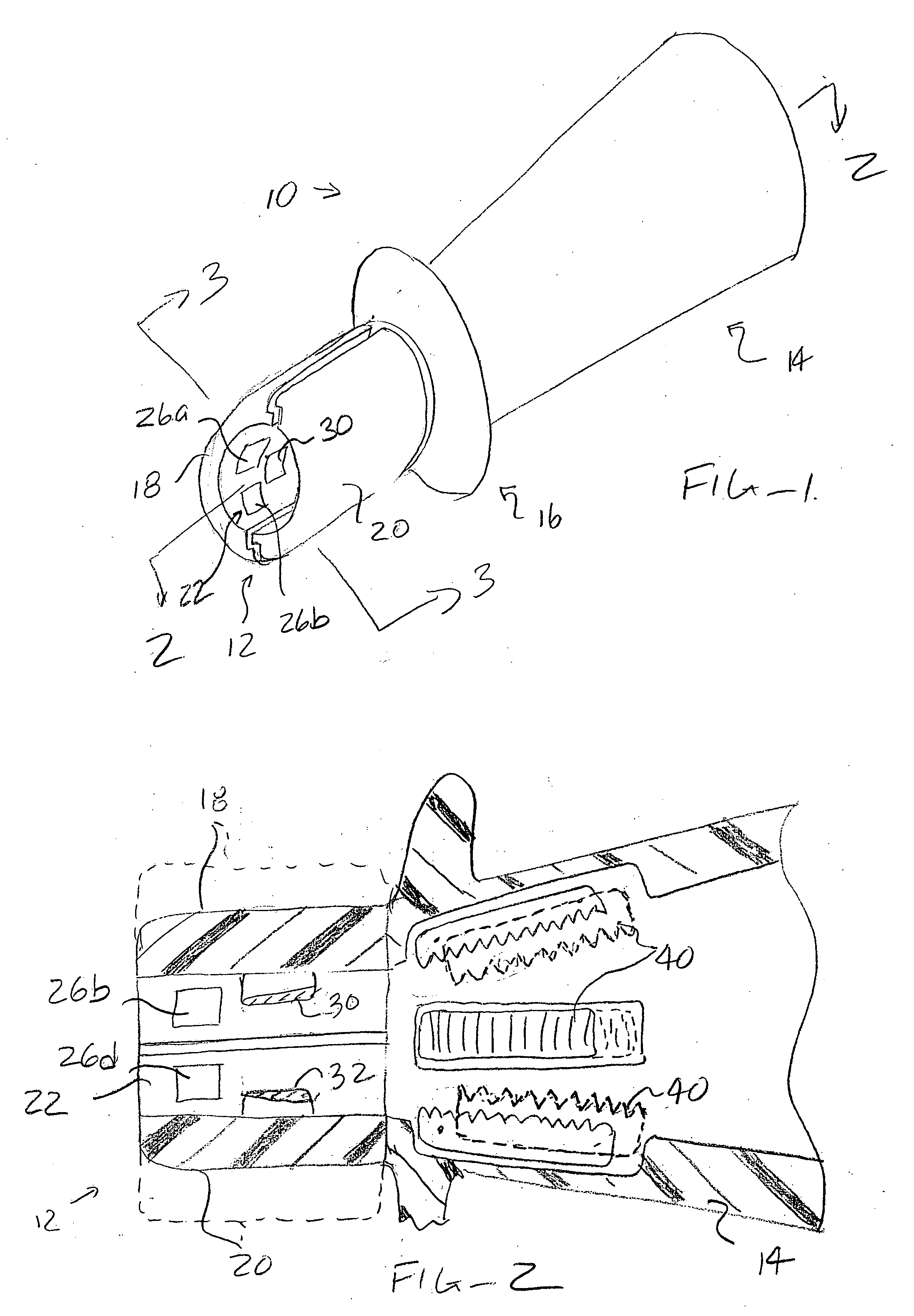
[0021] A transvaginal hysterectomy system 10 constructed in accordance with the principles of the present invention is illustrated in FIGS. 1-3. The system 10 includes a distal ring assembly 12, proximal body portion 14, and an insertion flange 16. The insertion flange will be used for positioning the device against the vaginal os when the distal ring assembly 12 is to be positioned within the vagina. In other embodiments where the device might be positioned outside of the vaginal os, the flange 16 would not be necessary.

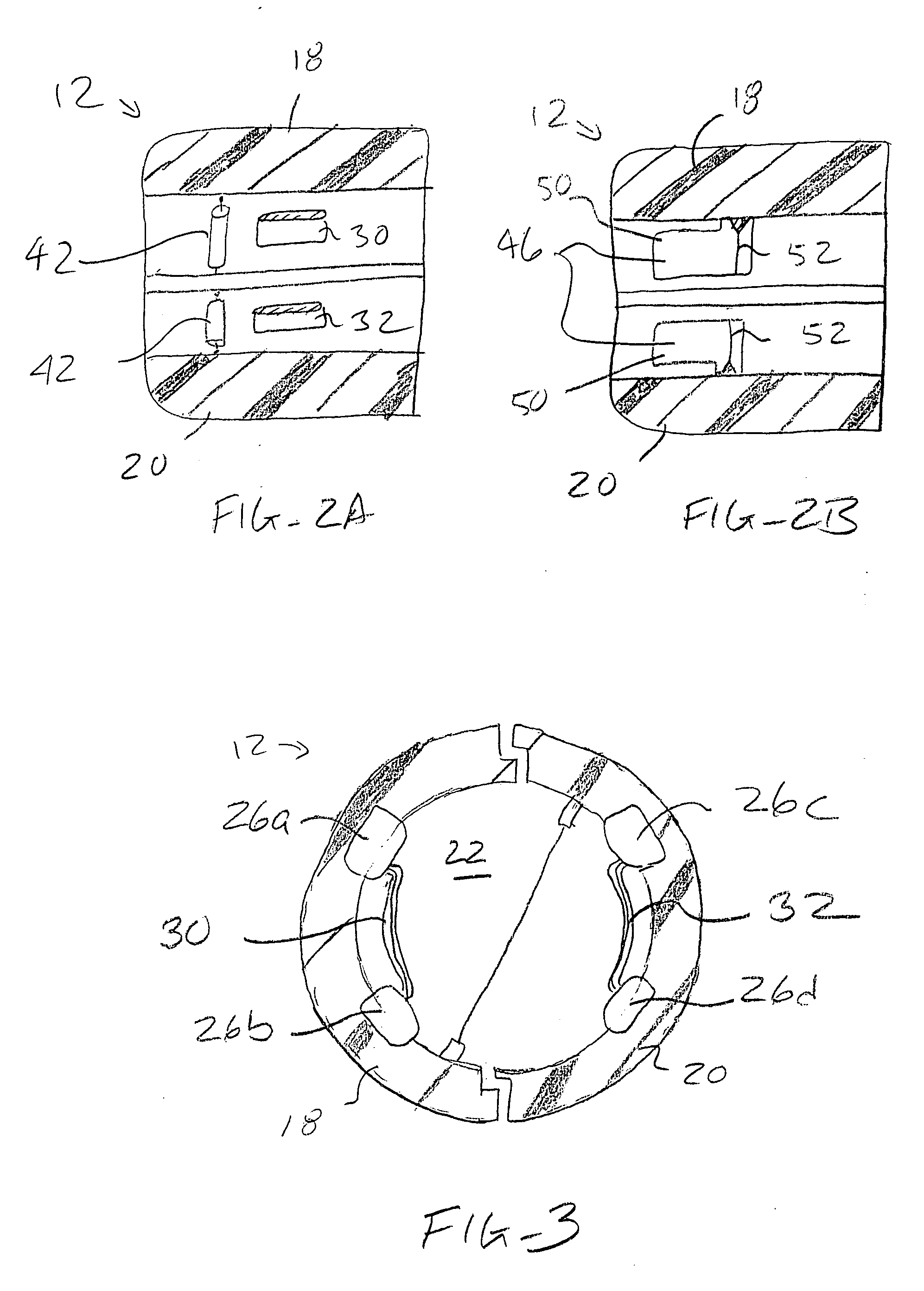
[0022] Referring now in particular to FIGS. 2 and 3, the distal ring assembly 12 comprises ring halves 18 and 20 which surround an opening 22. The ring halves 18 and 20 can move transversely apart, as shown in broken line in FIG. 2, and respond to passage of the uterus therethrough. Thus, the ring assembly 12 can accommodate different uterine sizes of different patients.

[0023] Four electrode pads 26a, b, c, and d are formed over an inner surface of the distal ring...


PUM


Abstract

Transvaginal hysterectomy is performed by mechanically engaging and extracting a uterus through opposed cutting and cauterizing elements. The cutting and cauterizing elements are typically provided on an expandable frame which may be positioned at the vaginal os. An associated traction device may be used to pull the uterus through the frame at a controlled rate.

Description

BACKGROUND OF THE INVENTION [0001] 1. Field of the Invention [0002] The present invention relates generally to medical apparatus and methods. More particularly, the present invention relates to methods, systems, and devices for performing vaginal hysterectomy by extracting a uterus through opposed cutting and cauterizing elements. [0003] A surgical procedure for removing a uterus is referred to is a “hysterectomy.” hysterectomy is most commonly performed via an abdominal incision but can also be performed via laparoscopy or transvaginally. The present invention is particularly concerned with transvaginal hysterectomy where the uterus is accessed through the vagina, the cervix is resected from surrounding tissues, and the uterus is removed through the vagina by manually pulling on the cervix and body of the uterus using forceps. [0004] While transvaginal hysterectomy is advantageous in that it does not require a surgical incision or laparoscopic penetration, many physicians have diff...

Claims


Application Information

Patent Timeline
IPC IPC(8): A61B18/14
CPCA61B18/1442A61B2018/00208A61B2018/1861A61B2018/00595A61B2018/00601A61B2018/00559
Inventor MARONEY, JOHNEDER, JOSEPHNEZHAT, CAMRAN
Owner FORCEPT
Learn More