System and method for detecting impaired electric power equipment

a technology of electrical equipment and detection method, applied in the field of system and method for detecting impaired electrical equipment, can solve the problems of limiting or disrupting the operation of the electrical system, electromagnetic radiation may interfere with the operation of other electrical systems, and many sophisticated electrical systems are becoming increasingly sensitive to the effects of electromagnetic radiation

Inactive Publication Date: 2006-11-30
EXACTOR INC
View PDF13 Cites 42 Cited by
  • Summary
  • Abstract
  • Description
  • Claims
  • Application Information

AI Technical Summary

Benefits of technology

[0007] Compounding this problem is the fact that EMI detection techniques have not advanced rapidly enough in light of the development of new types of electrical systems. There are currently few research and development activities to develop new devices to identify the causes of EMI. As a result, EMI is an increasing problem.
[0008] Power line arcing is one example of a cause of EMI. As a result of the high voltage, power line arcing may be destructive, and it may indicate that certain electrical equipment is in an impaired condition. In fact, any type of arcing may indicate that electrical equipment is in an impaired condition.
[0009] Arcing occurs when a sufficiently large potential difference develops between two objects. For example, a small gap between components of energized electrical equipment may lead to arcing, wherein an electrical charge builds up and discharges across the gap. The cause of a gap may simply be due to expansion and contraction or corrosion of the equipment. As a result, small gaps in the electrical equipment can be very difficult to identify. Compounding the difficulty is the fact that some electrical equipment such as power lines may be located well above ground level and energized with high voltage, making it impractical or inefficient for electrical utility personnel to visually inspect each structure or other elevated equipment in an attempt to locate an impaired piece of electrical equipment. Impaired equipment can still be difficult to locate even if the equipment is located near ground level. For instance, multiple pieces of electrical equipment in a general area such as a room, a factory building, or even a general outside area can hinder the detection of an impaired piece of equipment. As a result, the location of impaired electrical equipment may be difficult to identify.
[0010] In light of the difficulty in locating impaired electrical equipment, there is a need for a system and method for detecting impaired electrical equipment that may utilize the characteristics of the arcing. The pulse repetition rate is the rate at which arcing occurs across a gap, which may be measured by the number of arcs per unit time. The pulse repetition rate is typically proportional to the source voltage and inversely proportional to the width of the gap. Consequently, with everything else being equal, a higher voltage results in a higher pulse repetition rate, and a wider gap results in a lower pulse repetition rate. In addition to the pulse repetition rate, arcing has an RF frequency characteristic. In particular, arcing results in the production of a radio frequency signal. In the case of EMI, the signal is typically broad spectrum such that it is detectable across a wide band of the radio frequency spectrum. Each arc produces a radio frequency signal; therefore, as the width of the gap or the source voltage changes, the resulting radio frequency signal also changes. Other factors may also affect the RF frequency. For example, with regard to a utility pole, the RF frequency may also be affected by: the height of the utility pole; whether or not a ground wire runs along a side of the utility pole; the distance between the utility pole and adjacent poles; the components (e.g., insulators, cutouts, etc.) that are mounted at the top of the utility pole; and whether the utility pole is a single-phase or three-phase structure. Other factors may also impact the RF frequency. All of these parameters can and often do act as ‘antenna tuning elements’ that affect the signal that is radiated when an arc occurs. As a result, during any given 60 Hz cycle, for example, there may be a family of different RF signals produced. Finally, arcing may have a modulation frequency. The modulation frequency of the arcing is not dependent on the level of the source voltage or the width of a gap between electrical components. In this sense, the modulation frequency is an independent characteristic of the radio frequency signal(s) produced by arcing. In other words, with regard to arcing caused by an alternating current (AC) source, the modulation frequency is a characteristic of the frequency of the source.
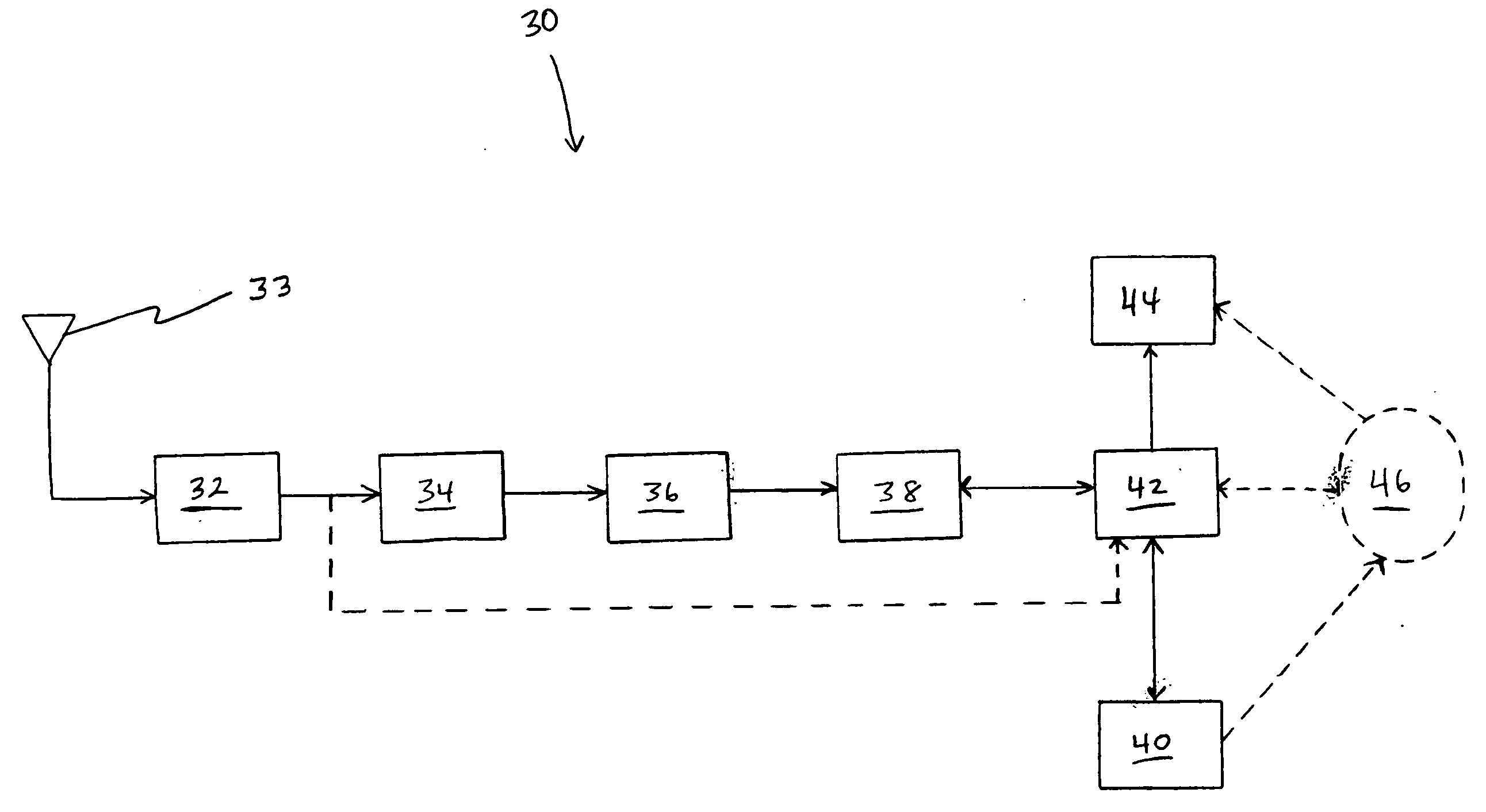
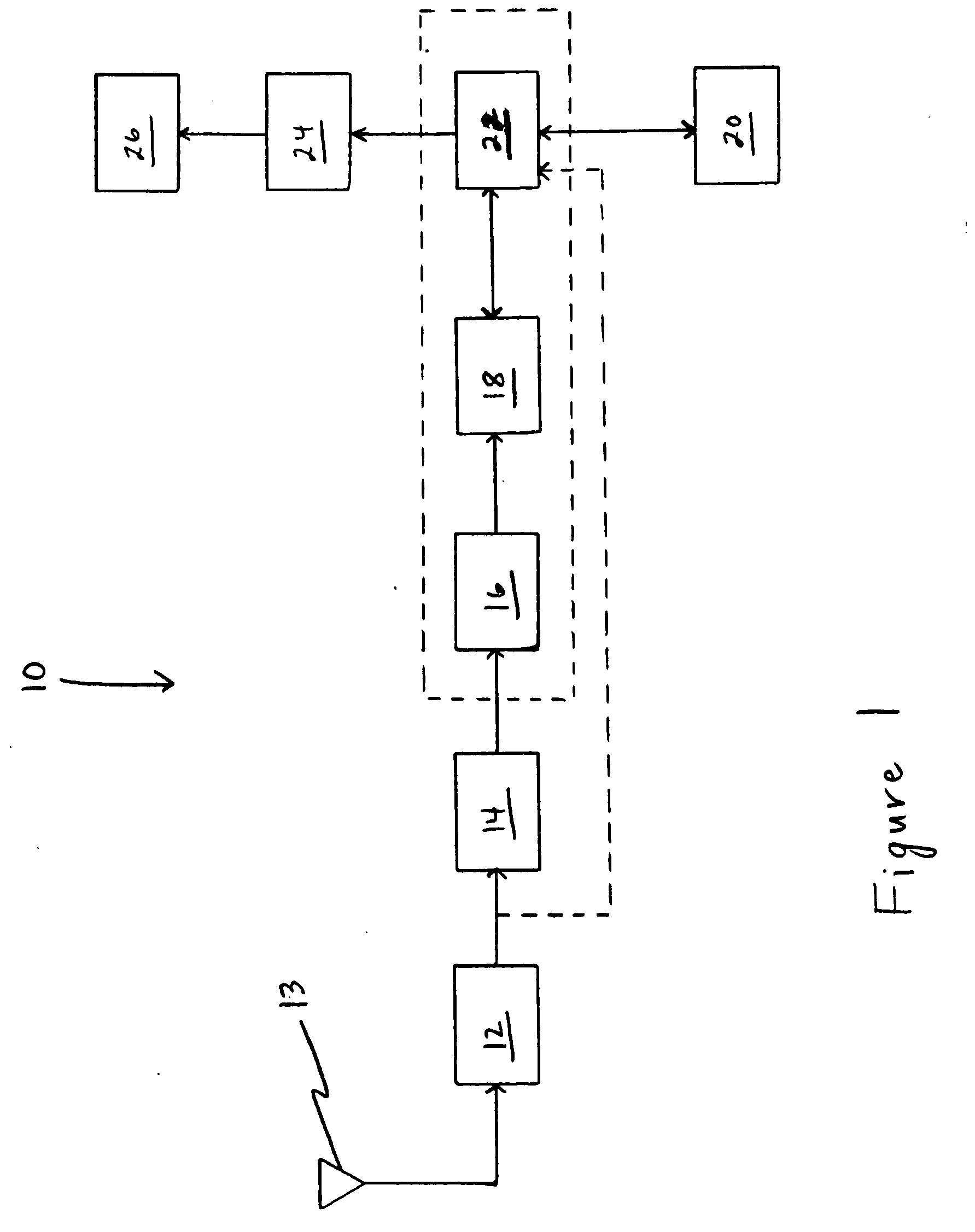
[0011] The present invention is directed to a system and method for detecting impaired electrical equipment. An exemplary embodiment of the present invention may receive electromagnetic radiation and process the resulting signal. For example, signal processing in some embodiments of the present invention may be used to identify electromagnetic radiation having a particular characteristic. Furthermore, an exemplary embodiment of the present invention may also include the determination of the time and / or location during testing. As a result, an exemplary embodiment of the present invention may be useful for stationary and / or mobile testing of an electrical system.
[0012] In addition to the novel features and advantages mentioned above, other features and advantages of the present invention will be readily apparent from the following descriptions of the drawings and exemplary embodiments.

Problems solved by technology

The underlying cause of the electromagnetic radiation may limit or disrupt the operation of the electrical system that is emitting the electromagnetic radiation.
Moreover, electromagnetic radiation may also interfere with the operation of other electrical systems.
In fact, many sophisticated electrical systems are becoming increasingly sensitive to the effects of electromagnetic radiation.
In addition, impaired electrical equipment may be the cause of an increased level of electromagnetic radiation.
Regardless of whether the cause of electromagnetic radiation is intentional or inadvertent, hostile or friendly, or caused by jamming devices, malfunctioning equipment, or improper system operation, the resulting electromagnetic radiation can have detrimental impact on the operation of electronics and other electrical systems.
However, the development of new shielding technologies has not kept pace with the development of new electrical systems.
Thus, the development of shielding has been relatively stagnant in recent history.
Compounding this problem is the fact that EMI detection techniques have not advanced rapidly enough in light of the development of new types of electrical systems.
There are currently few research and development activities to develop new devices to identify the causes of EMI.
As a result, EMI is an increasing problem.
Power line arcing is one example of a cause of EMI.
As a result of the high voltage, power line arcing may be destructive, and it may indicate that certain electrical equipment is in an impaired condition.
In fact, any type of arcing may indicate that electrical equipment is in an impaired condition.
For example, a small gap between components of energized electrical equipment may lead to arcing, wherein an electrical charge builds up and discharges across the gap.
The cause of a gap may simply be due to expansion and contraction or corrosion of the equipment.
As a result, small gaps in the electrical equipment can be very difficult to identify.
Compounding the difficulty is the fact that some electrical equipment such as power lines may be located well above ground level and energized with high voltage, making it impractical or inefficient for electrical utility personnel to visually inspect each structure or other elevated equipment in an attempt to locate an impaired piece of electrical equipment.
Impaired equipment can still be difficult to locate even if the equipment is located near ground level.
For instance, multiple pieces of electrical equipment in a general area such as a room, a factory building, or even a general outside area can hinder the detection of an impaired piece of equipment.
As a result, the location of impaired electrical equipment may be difficult to identify.

Method used


Image

  • System and method for detecting impaired electric power equipment
  • System and method for detecting impaired electric power equipment
  • System and method for detecting impaired electric power equipment

Examples


Embodiment Construction

)

[0017] The present invention is directed to a system and method for detecting impaired electric power equipment. FIG. 1 illustrates one example of a system of the present invention. In FIG. 1, the system 10 is comprised of a signal detection circuit 12. Signal detection circuit 12 may be any device that is adapted to receive radio frequency electromagnetic radiation or radiation in another desired frequency range. The particular type of signal detection circuit 12 may be selected to detect electromagnetic radiation within a desired frequency range. For example, the signal detection circuit 12 of an exemplary embodiment of the present invention may be adapted to detect electromagnetic radiation in a frequency range outside of the normal operating frequency range of the energized electrical equipment to be tested. Furthermore, in some embodiments of the present invention, it may desirable for the signal detection circuit 12 to detect electromagnetic radiation in a frequency range tha...


PUM


Abstract

The present invention is directed to a system and method for detecting impaired electric power equipment. An exemplary embodiment of the present invention may receive electromagnetic radiation and process the resulting signal. For example, signal processing may be used to identify electromagnetic radiation having a particular pattern that is characteristic of electric power equipment. Furthermore, an embodiment of the present invention may determine the time and/or location during testing. As a result, the present invention may be useful for stationary and/or mobile testing of an electrical system.

Description

BACKGROUND AND SUMMARY OF THE INVENTION [0001] The present invention relates generally to a system for identifying impaired electrical equipment. More particularly, the present invention relates to a system and method for detecting impaired electric power equipment. Exemplary embodiments of the present invention may also be useful for testing various other types of electrical systems. Furthermore, exemplary embodiments of the present invention may be useful for stationary and / or mobile testing of various types of electrical systems. [0002] Power generation, distribution, transmission, and substation systems are just some examples of electrical systems. Some other examples of electrical systems include radio systems, communication systems, control systems, industrial electrical systems, and other types of electrical circuitry and systems. In addition, many other types of electrical systems are known or may be developed. [0003] Any type of electrical system may be responsible for crea...

Claims


Application Information

Patent Timeline
Patent Type & Authority Applications(United States)
IPC IPC(8): G01R21/00
CPCG01R29/0871
Inventor HAYES, RAYMOND M.KLINECT, DAVID A.
Owner EXACTOR INC
Why Eureka
Try Eureka