Valve with end position switching

a technology of end position switch and valve, which is applied in the direction of water mains, gas/liquid distribution and storage, service pipe systems, etc., can solve the problems of not having the installation space available for an end position switch, requiring adjustment, and unable to meet the requirements of only difficulty, so as to prevent the damage of the end position switch due to hard impacts during transport or during installation, and the effect of easy sealing the tapp

Inactive Publication Date: 2006-12-07
KARL DUNGS
View PDF1 Cites 34 Cited by
  • Summary
  • Abstract
  • Description
  • Claims
  • Application Information

AI Technical Summary

Benefits of technology

[0009] Thanks to this measure, uniform end position switches can be arranged on valves and valve drives with a wide range of valve strokes. In each, the end position switch is activated in the first millimeters of the stroke and independent of how large the stroke is overall. The end position switch can be placed on the top side of the valve, i.e., set on top on the drive. Thus, a visual opening indication of the valve is also possible. The space underneath the valve closing element remains free. A pressure regulating unit can be installed there. In addition, destruction of the end position switch due to hard impacts during transport or during installation is prevented.
[0010] As mentioned, uniform switches can be used for valves with strokes having different nominal widths. These switches are switched within an extremely tight window at the beginning of the stroke. Special structural modifications of the switch are unnecessary. Also, due to the small stroke of the tappet relative to the switch, it is easy to seal the tappet. The short stroke movement of the tappet leads to only minimal wear on corresponding sealing elements, such as O-rings or sealing membranes. In addition, the switches according to the invention are built small, because they have to permit only a small stroke. The setup costs for adjusting such switches is low. It is possible to preset the switches at the factory, so that they merely have to be installed by the valve manufacturer. The switch is preferably arranged at the top end of the linear drive. From there, it monitors the beginning of the opening movement of the body (although it is arranged at the end of the opening path).

Problems solved by technology

If, for example, a pressure regulator or a flow regulator is arranged in this region, there is no installation space available for an end position switch.
These requirements can be fulfilled only with difficulty and usually require adjustment.

Method used


Image

  • Valve with end position switching
  • Valve with end position switching
  • Valve with end position switching

Examples


Embodiment Construction

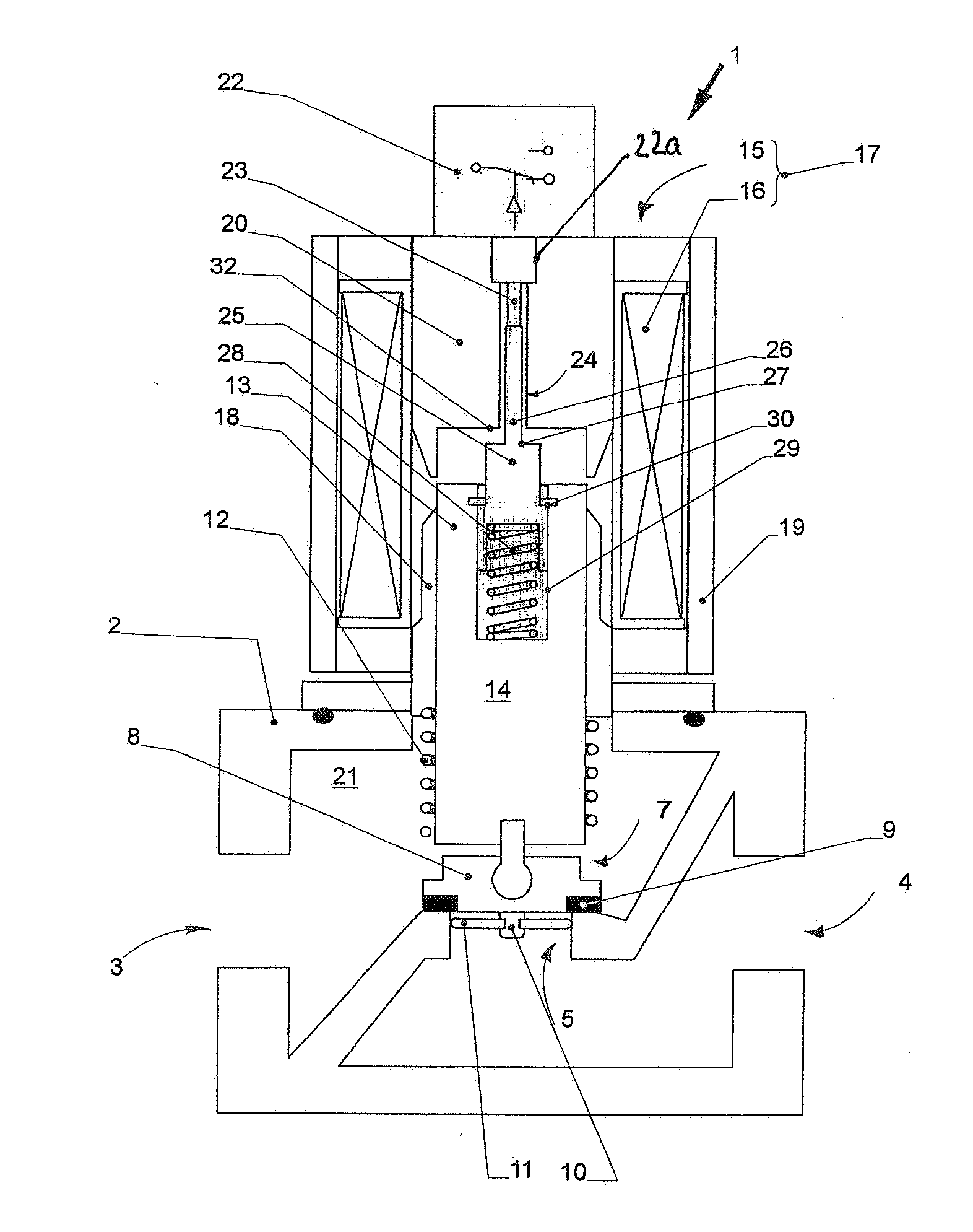
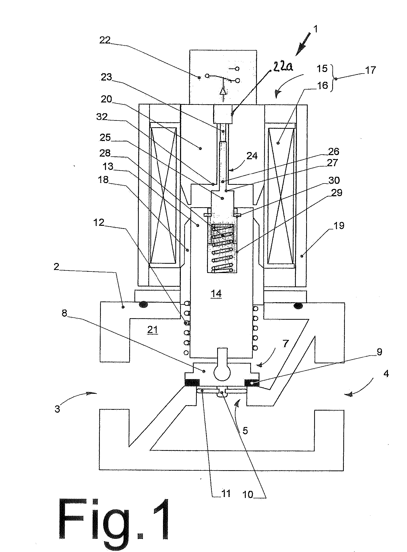
[0021] In FIG. 1, a valve 1 is shown, which acts, e.g., as a gas valve. It features a valve housing 2 with an inlet 3, an outlet 4, and a valve seat 5 formed therein. The latter is formed by an opening in an intermediate wall 6.

[0022] A valve closing element 7 is associated with the valve seat 5, for example, in the form of a valve plate 8, which is provided with a seal 9 sealing the valve seat 5. On valve plate 8 there can be a peg 10, which extends into the opening of the valve seat 5 and which supports a sealing disk 11. The latter sits within the opening established by the valve seat 5, and opens the gas passage only when it is pulled out of the valve seat 5.

[0023] The valve closing element 7 is biased, i.e., against the valve seat 5, towards its closed position, preferably by a compression spring 12. The compression spring 12 is supported with one end on the valve plate 8 and with its other end on the valve housing 2 or on an element fixed to this housing.

[0024] The valve pl...


PUM


Abstract

For detecting closing or opening of a valve activated preferably by a solenoid actuator, a switch activated by a tappet spring mounted on an armature of the actuator is provided. A stop and an associated surface limit the stroke of the tappet with reference to the switch. Preferably, a valve closing element opens the gas flow only when the armature has already executed a part of its opening stroke. The trigger point of the switch is set in this first part of the opening stroke of the armature, in which the valve closing element has not yet opened. The stroke limiting of the tappet for activating the switch is also preferably set in this region of the opening stroke of the armature. However, the stop limits the stroke of the tappet independent of the opening stroke size of the armature, so that the same switch can be used for different valves with different nominal diameters and opening strokes.

Description

CROSS-REFERENCE TO RELATED APPLICATIONS [0001] This application claims priority to German Application No. 10 2005 026 105.1, filed Jun. 7, 2005, which is incorporated herein by reference. FIELD OF THE INVENTION [0002] The invention relates to a valve with an end position switch for closure recognition. BACKGROUND OF THE INVENTION [0003] For safety reasons, it is occasionally necessary to mount end position switches on gas valves or other corresponding valves. These end position switches output a signal with a first signal value when the valve is securely closed and with a second signal value before the valve opens the gas flow. Here, the second signal value can be output when the valve is still closed, but an opening process has already begun. A signal must be changed from its first state to a second state within an extremely precisely defined window with reference to the stroke of the valve closing element, or other elements which are connected to the valve closing element. This wi...

Claims


Application Information

Patent Timeline
Patent Type & Authority Applications(United States)
IPC IPC(8): F16K37/00
CPCF16K37/0041F16K31/0655Y10T137/8242
Inventor SONTAG, ROLF
Owner KARL DUNGS
Why Eureka
Try Eureka