Ocean wave generation

a generator and ocean wave technology, applied in the direction of electric generator control, machines/engines, mechanical equipment, etc., can solve the problems of not reducing the efficiency of the generator, untapped renewable energy sources, ocean wave generators,

Active Publication Date: 2006-12-07
GEHRING DONALD HOLLIS
View PDF31 Cites 48 Cited by
  • Summary
  • Abstract
  • Description
  • Claims
  • Application Information

AI Technical Summary

Problems solved by technology

However, an untapped source of renewable energy is the power from harnessing ocean waves.
None of the above inventions, however, provide fo...

Method used


Image

  • Ocean wave generation
  • Ocean wave generation
  • Ocean wave generation

Examples


Embodiment Construction

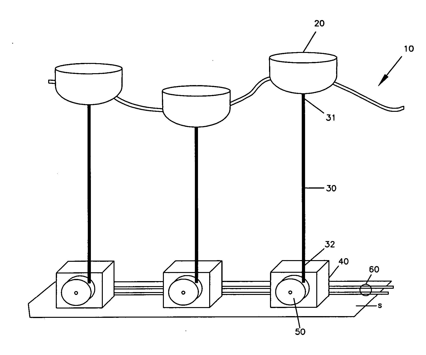
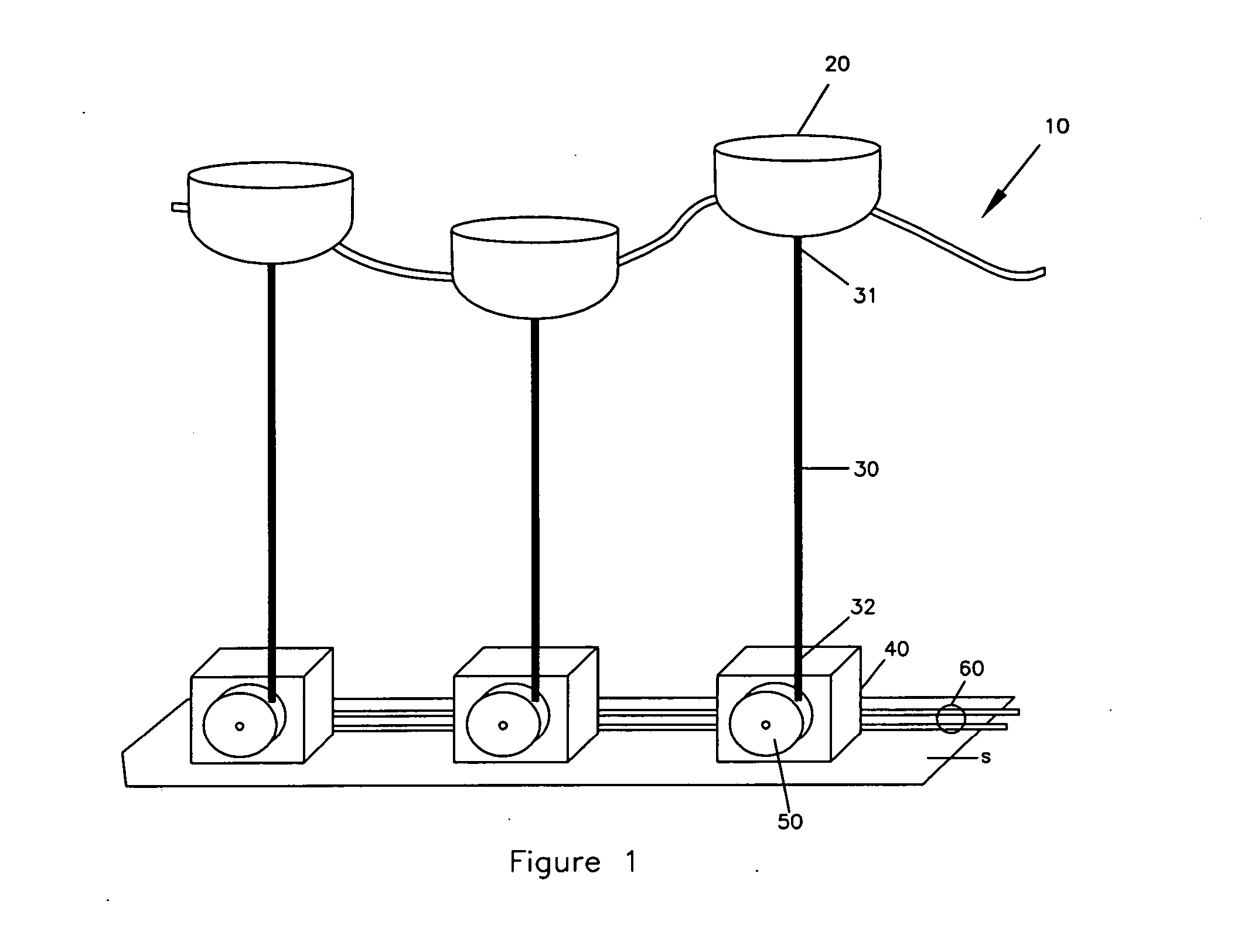
[0026] Referring now to the drawings, wherein like reference numerals refer to the same components across the several views and in particular to FIGS. 1 and 2, there is shown an ocean wave generator 10. The ocean wave generator 10 includes a buoy 20, an anchor cable 30, a generator 40, a pulley 50, and power cables 60.

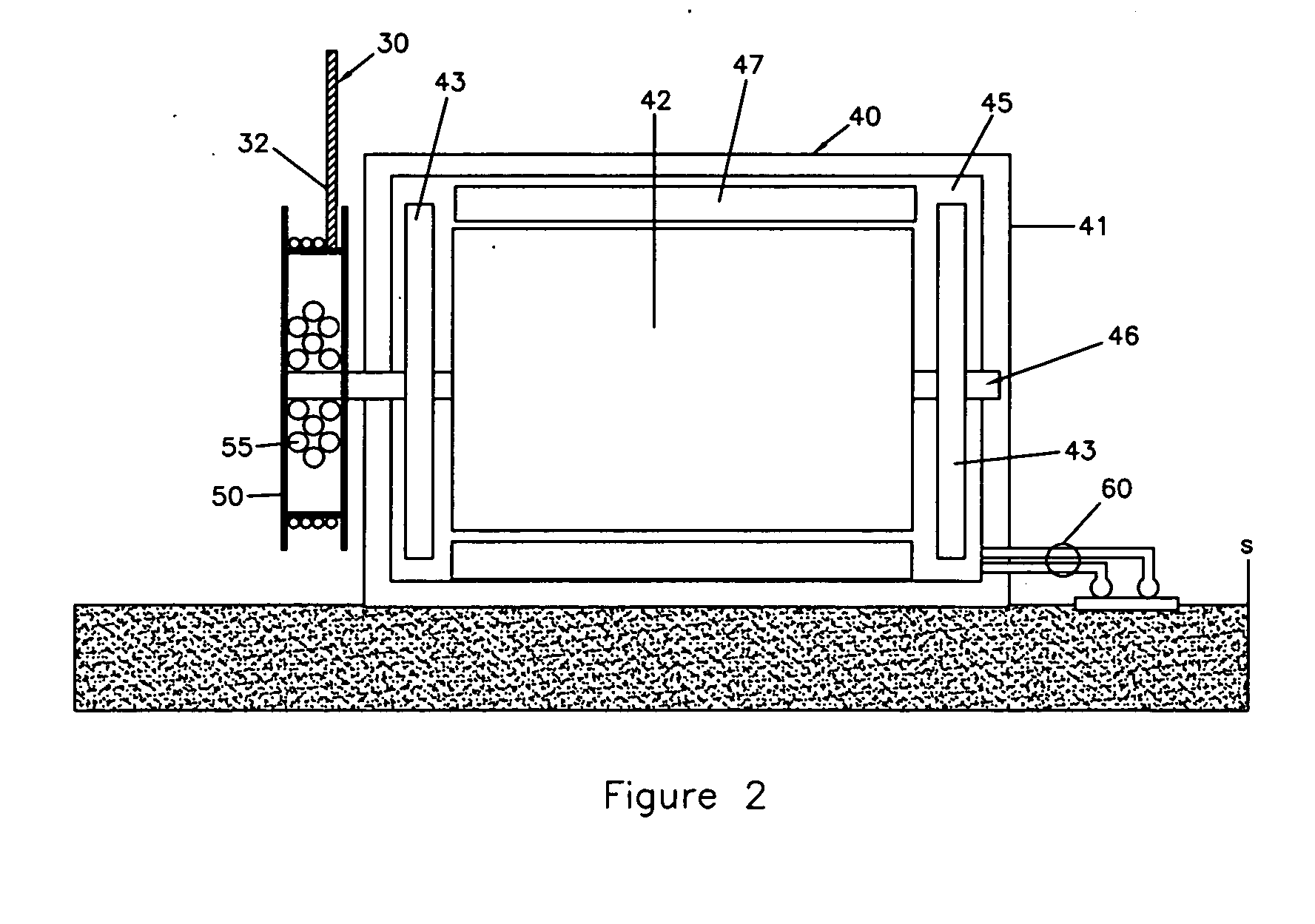
[0027] The buoy 20 floats on the surface of the ocean and rises and falls as the waves rise and fall. The anchor cable 30 is connected to the underside of the buoy 20 at a first end 31. A second end 32 is connected to the pulley 50, which is mounted on the generator 40.

[0028] The generator 40 includes an outer case 41 and an inner chamber 45. The inner chamber 45 of the generator 40 houses a rotor 42 which turns to generate electricity. The rotor 42 is connected to a shaft 46. Disposed at one end of the shaft 46 is the pulley 50. The second end 32 of the anchor cable 30 is wrapped around the pulley 50. As the buoy 20 rises and falls, the anchor cable 30 rotates the p...


PUM


Abstract

An ocean wave generator is disclosed. The ocean wave generator includes a buoy, floating on the surface of the ocean; a generator; a pulley mounted on the generator for turning the generator; an anchor cable having a first end and a second end, wherein the first end of the anchor cable is connected to the underside of the buoy and the second end is mounted to the pulley; and a power cable, in electrical communication with the generator.

Description

FIELD OF THE INVENTION [0001] The present invention relates to generators, and in particular to an ocean wave generator that converts ocean waves into electrical energy. BACKGROUND OF THE INVENTION [0002] Society increasingly is more dependent on energy sources as nations become more advanced. As fuels required to generate energy become expended, man looks to more renewable sources with which to produce energy. Among some of the sources are wind power, solar power, and hydroelectric power. However, an untapped source of renewable energy is the power from harnessing ocean waves. [0003] U.S. Pat. No. 5,066,867 discloses a method and device for generating electric power by use of wave force. According to the invention, it is possible to obtain the required power using the floatation bladders rising and falling repeatedly with waves as a power using the floatation bladders rising and falling repeatedly with waves as a power source and the rotation force of gears connected to the floatat...

Claims


Application Information

Patent Timeline
IPC IPC(8): F03B13/12F03B13/10H02P9/04
CPCF03B13/1885F03B17/061Y02E10/38Y02E10/28F05B2240/40Y02E10/30Y02E10/20
Inventor GEHRING, DONALD HOLLIS
Owner GEHRING DONALD HOLLIS
Why Eureka
Try Eureka