Wave energy transducer

a wave energy transducer and wave energy technology, applied in the direction of electric generator control, machines/engines, mechanical equipment, etc., can solve the problems of not being able to commercially feasible systems for extracting the power of moving waves in a body of water on a commercial basis, and it is much more difficult to harness the vast power of ocean waves

Inactive Publication Date: 2002-12-26
AGUIRRE ABEL L
View PDF0 Cites 35 Cited by
  • Summary
  • Abstract
  • Description
  • Claims
  • Application Information

AI Technical Summary

Problems solved by technology

While numerous systems exist for successfully converting the energy of a current of water that flows continuously in the same direction to electrical current, it has proven much more difficult to harness the vast power of the ever oscillating motion of ocean waves.
However, because the waves of an ocean, sea, or lake move to and fro at different heights and surge with irregular frequency at different periods of time, a system for extracting the power of moving waves in a body of water on a commercially feasible basis has not heretofore been achieved.

Method used


Image

  • Wave energy transducer
  • Wave energy transducer
  • Wave energy transducer

Examples


Embodiment Construction

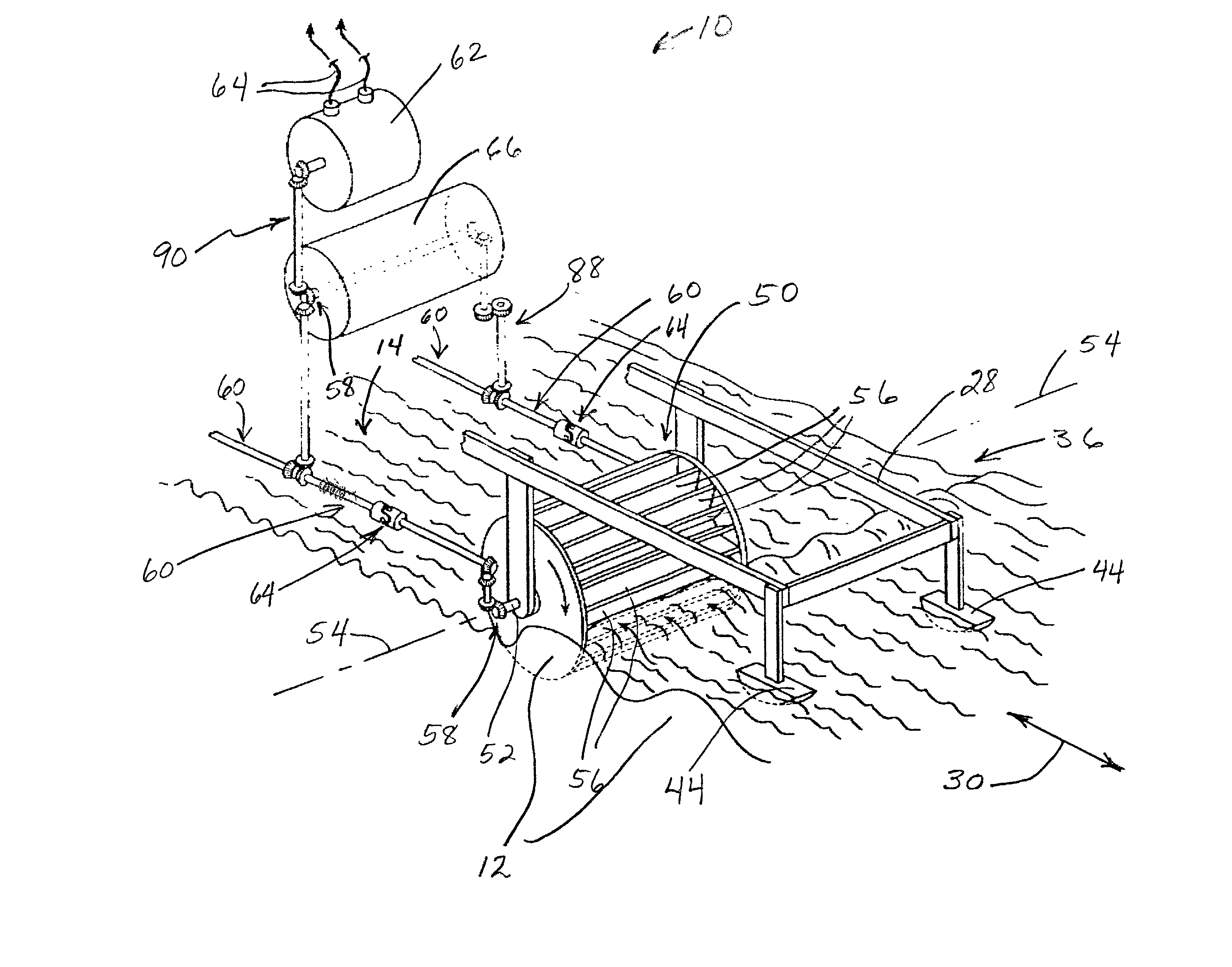
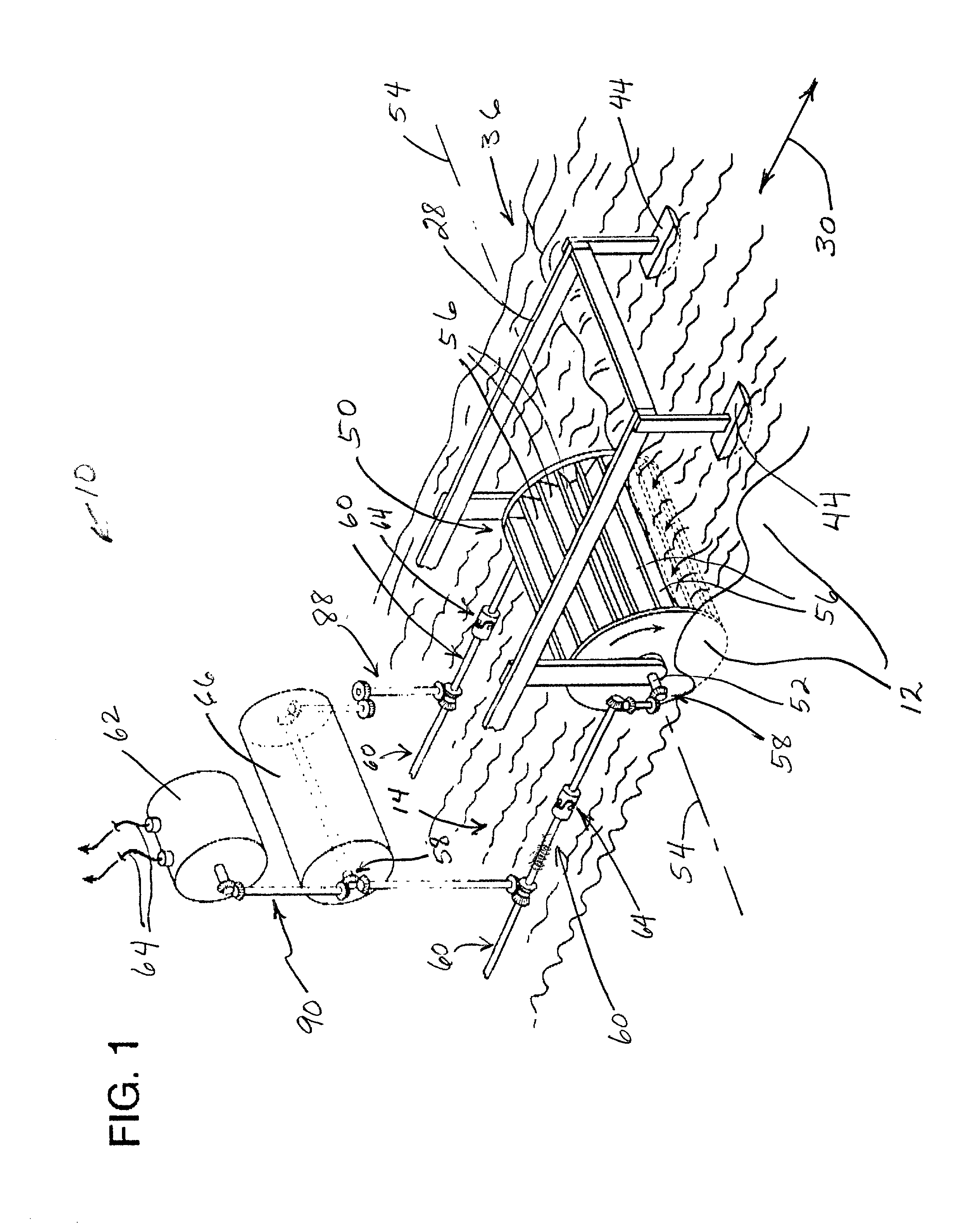
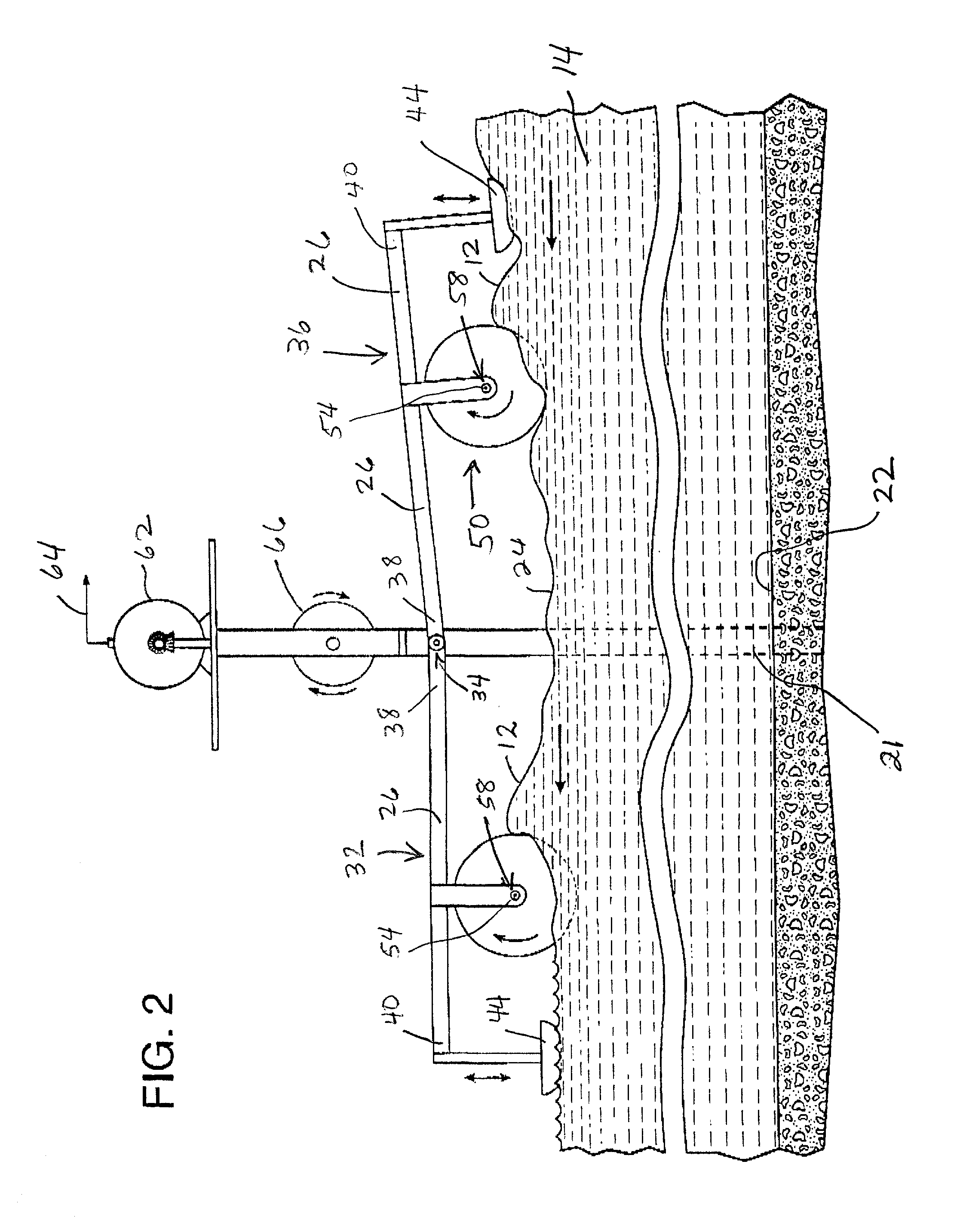
[0028] FIG. 1 illustrates a wave energy transducer indicated generally at 10 for converting the energy of waves 12 moving in a body of water 14, which may be an ocean, a sea, or a lake. The wave energy transducer 10 includes a pair of upright posts or stanchions 16 having lower extremities 21, as illustrated in FIG. 3, which are anchored relative to the floor 22 of the body of water 14. The posts 16 are aligned with each other generally parallel to the shore and in a direction perpendicular to the predominant direction of wave action, which is indicated at 30 in FIG. 1. The posts 16 extend upwardly above the surface 24 of the body of water 14.

[0029] Two pairs 32 and 36 of mounting arms 26 and 28 are connected to the upright posts or stanchions 16. Both pairs of mounting arms 26 and 28 are rotatably secured by couplings 34 to the upright posts 16. The mounting arms 26 and 28 of the first mounting arm pair 32 extend in a direction toward shore and generally parallel to the predominant...


PUM


Abstract

A wave energy transducer is provided for converting the kinetic energy of waves moving in a body of water, such as waves in the ocean, to usable power. The wave energy transducer of the invention employs a pair of upright posts anchored to the floor of the ocean in a region subject to heavy wave activity. The posts are aligned perpendicular to the predominant direction of wave action. Mounting arms are hinged to the posts and extend in pairs toward shore and away from shore. Each of the pairs of mounting arms carries a paddlewheel, and the ends of the mounting arms are supported by floats. The floats hold the paddlewheels with their axes of rotation continually above the surface of the water and with their downwardly extending paddlewheel blades dipping into the water. Unidirectional drive mechanisms on each end of the paddlewheel axle are coupled to corresponding drive lines that in turn are connected to a power transducer, such as an electrical generator. Power is thereby extracted both from waves moving toward shore and from waves receding away from shore.

Description

[0001] 1. Field of the Invention[0002] The present invention relates to a system for converting the kinetic energy of waves moving in a body of water to usable power, such as electrical current.[0003] 2. Description of the Prior Art[0004] Various systems have been devised to attempt to extract the vast kinetic energy of water moving in a body of water and convert that energy to a usable form. While numerous systems exist for successfully converting the energy of a current of water that flows continuously in the same direction to electrical current, it has proven much more difficult to harness the vast power of the ever oscillating motion of ocean waves. Different systems have been devised that employ rotatable paddlewheels to convert the kinetic energy of ocean waves to electrical energy. However, because the waves of an ocean, sea, or lake move to and fro at different heights and surge with irregular frequency at different periods of time, a system for extracting the power of movin...

Claims


Application Information

Patent Timeline
Patent Type & Authority Applications(United States)
IPC IPC(8): F03B13/18
CPCY02E10/38F03B13/184Y02E10/30
Inventor AGUIRRE, ABEL L.
Owner AGUIRRE ABEL L
Why Eureka
Try Eureka