Offshore floating platform with ocean thermal energy conversion system

a technology of thermal energy conversion and offshore floating platform, which is applied in the direction of sea energy generation, mechanical equipment, machines/engines, etc., can solve the problems of not being able to achieve cost effective commercialization. , to achieve the effect of reducing the length, increasing the stability of the platform, and significantly reducing the capital cos

Active Publication Date: 2011-05-26
SRINIVASAN NAGAN
View PDF14 Cites 34 Cited by
  • Summary
  • Abstract
  • Description
  • Claims
  • Application Information

AI Technical Summary

Benefits of technology

[0017]The present system overcomes the aforementioned problems and is distinguished over the prior art in general, and these patents in particular, by an OTEC hybrid cycle power-plant engine that is supported on a floating platform or vessel which significantly reduces the length or completely eliminates the massive cold water pipe and allows the condenser to be placed near the surface of the seabed at about 3,000 ft. below the free water surface. The floating platform has at least one buoyant column with an upper end extending above a sea surface, a lower end submerged below the sea surface, and at least one keel tank disposed at the lower end. A deck is supported at the upper end the column. An ocean thermal energy conversion (OTEC) system is integrated with the platform in which heat is extracted from warm sea surface waters to vaporize a working fluid liquid and heat is rejected to cold water collected from lower depths of the sea to condense the working fluid vapor. In some embodiments, a turbine and a power generator are disposed on the deck, an evaporator is disposed on the platform beneath the deck, and a condenser is disposed on the platform or keel tank a distance beneath the evaporator. The weight of the condenser acts as a fixed ballast to increase the stability of the platform.
[0018]In some embodiments, the present OTEC engine incorporates subsea condensers, subsea pumps, submerged evaporators and independently movable or flexible buoyant free standing vertical flow pipes to transport working fluid from the turbine outlet to the subsea condensers. The condenser is located in a subsea area where the enormous cold water is available without the need of storage. The condenser is directly exposed to the underwater environment of about 4° C. and is designed to withstand 1,500 psi water pressure and operate at approximately 3,000 ft. depths. The condenser is also provided with propellers that conduct the cold water of about 4° C. of the environment across the exposed condenser. Thus, the need for pumping in and pumping out of water inside the condenser required in conventional OTEC systems is eliminated.
[0019]The present OTEC system reduces the capital cost significantly and provides significant differences and advantages over the conventional OTEC systems and makes it commercially feasible to provide OTEC systems having about 100 MW power plants. The present OTEC system which is supported in new types of floating vessels, or “floaters” achieves cost efficiency and reduces the capital cost of the OTEC system compared to conventional OTEC systems.

Problems solved by technology

However, the technology is not in commercial operation due to the large capital cost.
However, none of these improvements have made OTEC technology attractive for cost effective commercialization.
The vortex induced oscillations also could be a significant problem due to underwater ocean current.
Secondly, the heat exchanger, especially the condenser, required for the large OTEC plants is expensive due to its size and weight.
Another problem is that a large amount of water needs to be moved from the deep-ocean layer to the surface and handled on the vessel to be used in the condenser.
This also makes the conventional OTEC system inefficient and cost sensitive.
Bringing the OTEC system capital cost down is a real challenge faced by engineers and scientists.
Several costs are involved in a typical conventional OTEC system OTEC system.
The capital cost of the 100 W conventional power plant depends a great deal on the cost of the heat exchanger unit.
Even if a cost effective cold water pipe of composite material were utilized, the cost is still not significantly controllable for large units.
Small units are not beneficial to the location, and not cost effective due to the size of the supporting vessel.
Because of the large size of the cold water pipe, it is difficult to handle from the surface floating vessel in harsh environments.
If buoy-type connect and disconnect features are added to the cold water pipe, that cost is also added to the design.
Again, the vessel designed to support the conventional OTEC is sensitive to storms and harsh environments.
That poses large operational costs to the OTEC system in a deep sea.
Thus, the overall $420 million US dollar capital cost for a 100 MW power plant is not attractive for commercialization.
The amount of water needed to cool the working fluid is enormous.
The cold water pipe is massive and is subject to vortex induced oscillations due to underwater ocean current and huge stresses at the joint between the cold water pipe and the OTEC platform resulting from a combination of severe weather, wave action, and the length, diameter, and mass of the cold water pipe.
Thus, in the conventional OTEC system, an enormous amount of heavy equipment is used for handling large volumes of water on the surface of the floating vessel, which requires an increase in the vessel size and consequently a very high capital cost.
This requirement for large capital costs has contributed to the lack commercial operation of the OTEC technology.
However, none of these improvements have made OTEC technology attractive for cost effective commercialization.

Method used


Image

  • Offshore floating platform with ocean thermal energy conversion system
  • Offshore floating platform with ocean thermal energy conversion system
  • Offshore floating platform with ocean thermal energy conversion system

Examples


Embodiment Construction

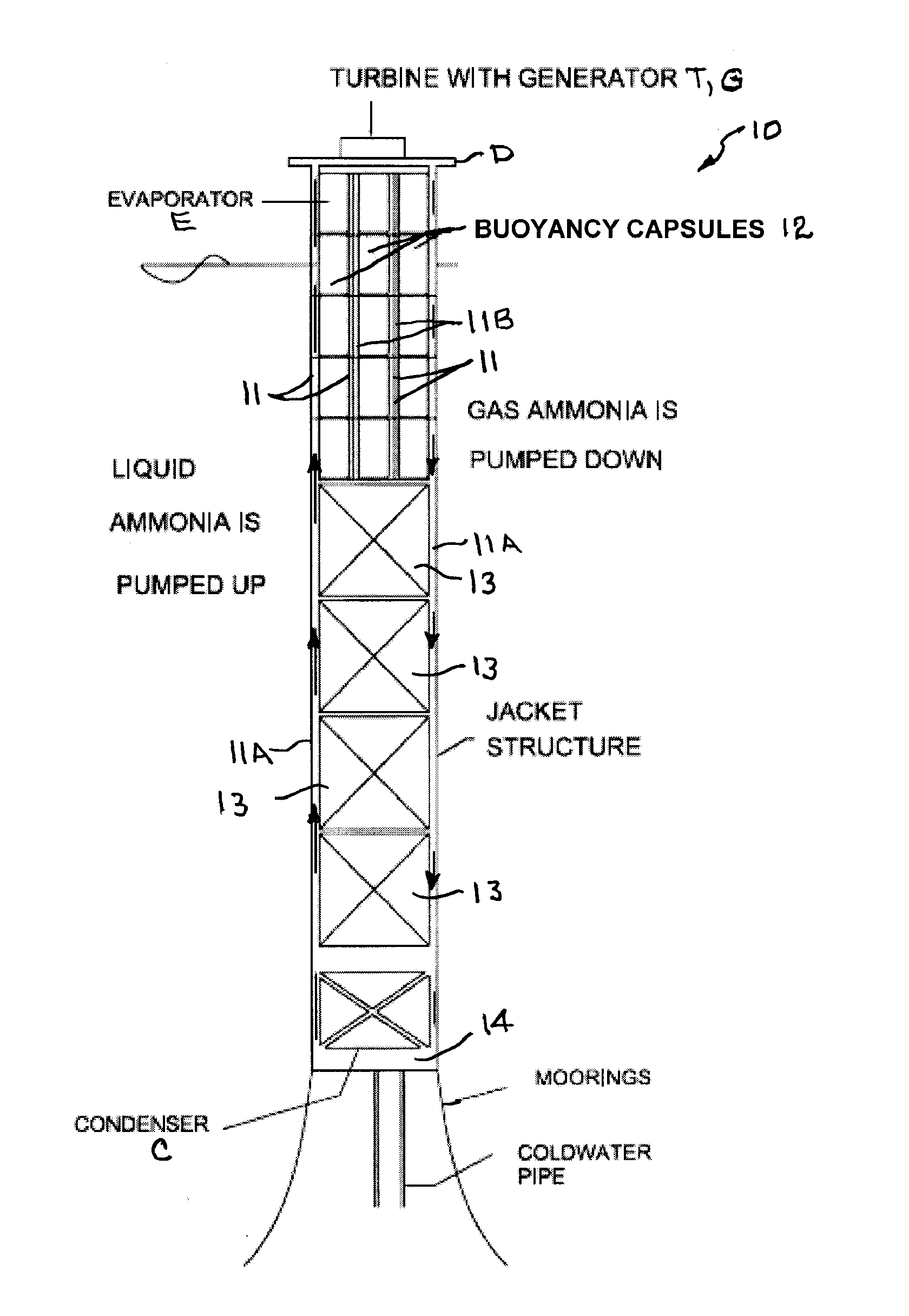
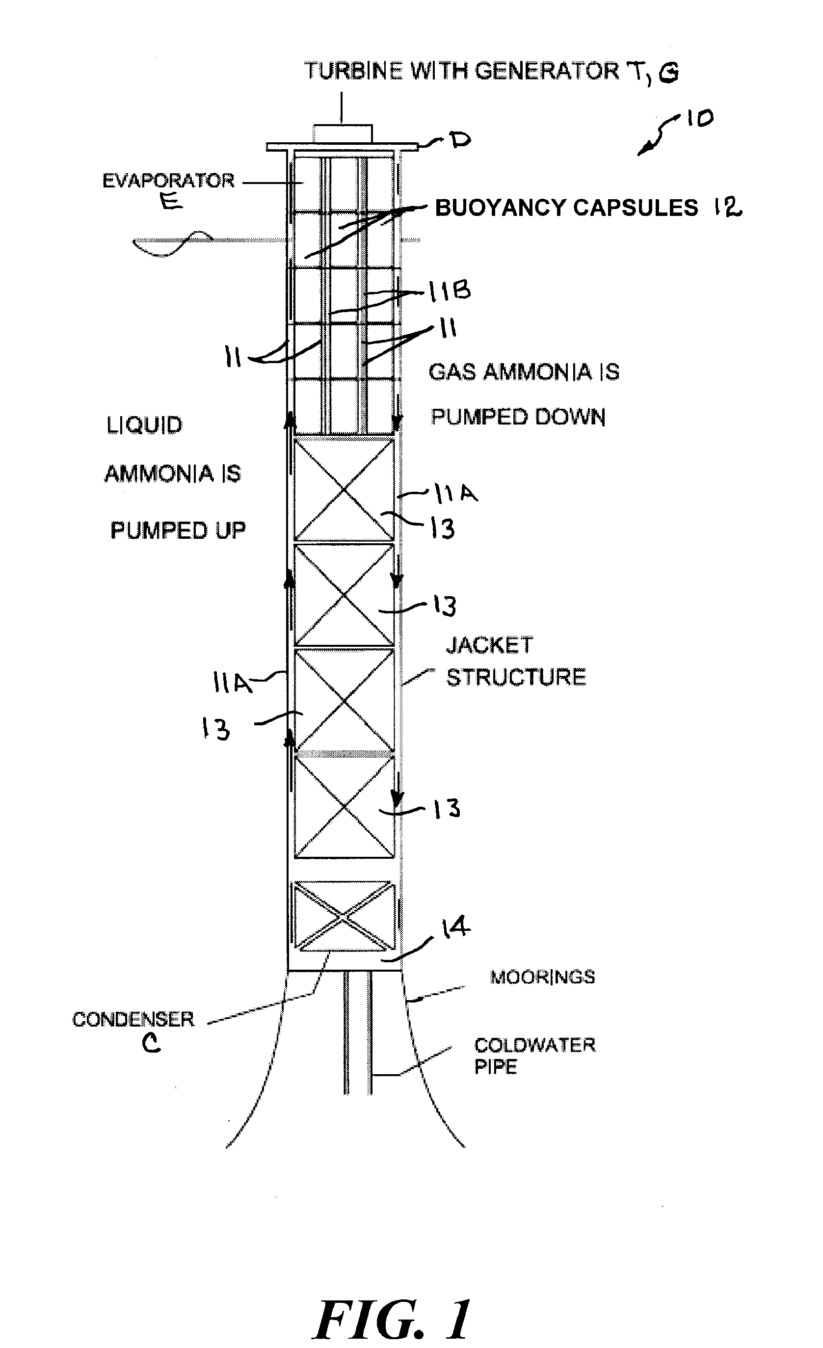
[0036]The present offshore floating platforms having an ocean thermal energy conversion system controls platform construction and operational costs by utilizing a supporting platform particularly suited for the OTEC system. For example, a few types of deepwater offshore platforms are easy to fabricate but expensive to install. There are some vessels that are designed to be self-installed and mobile. The present invention utilizes such a platform. The present invention also incorporates independently movable or flexible buoyant free standing vertical flow pipes to transport working fluid from the turbine outlet to the subsea condensers.

[0037]The main technical challenge in an OTEC system is the large amount of warm and cold sea water to be used for the heat transfer processes. Typically, a 100 MW OTEC system requires 5,000 cubic ft. per second of cold water to be transported to the free surface from the deep ocean depth. Similarly, 8,000 cubic ft per second of surface warm water is t...


PUM


Abstract

An offshore floating platform having at least one buoyant column with an upper end extending above a sea surface, a lower end submerged below the sea surface, and at least one keel tank disposed at the lower end. A deck is supported at the upper end the column. An ocean thermal energy conversion (OTEC) system is integrated with the platform in which heat is extracted from warm sea surface waters to vaporize a liquid working fluid and heat is rejected to cold water from lower depths of the sea to condense the vaporized working fluid. At least one turbine and power generator is disposed on the deck, at least one evaporator is disposed on the platform beneath the deck, and at least one condenser is disposed on the seabed or platform or keel tank a distance beneath the evaporator.

Description

CROSS REFERENCE TO RELATED APPLICATION[0001]This application claims priority of U.S. Provisional Application Ser. No. 61 / 174,495 filed May 1, 2009, the pendency of which is extended until May 3, 2010 under 35 U.S.C. 119(e)(3).BACKGROUND OF THE INVENTION[0002]1. Field of the Invention[0003]This invention relates generally to offshore floating structures, and, more particularly to an offshore floating platform having an ocean thermal energy conversion system.[0004]2. Background Art[0005]Demand for energy worldwide and the need for alternate energy sources is increasing significantly. Ocean Thermal Energy Conversion (OTEC) is a viable alternate energy source which has been in the development stage for the past three to four decades. A great amount of energy is available in deep-ocean environments with temperature difference between an upper surface layer and a lower deep-ocean layer may be within a maximum range of approximately 25° C. in localized offshore locations near equatorial wa...

Claims


Application Information

Patent Timeline
Patent Type & Authority Applications(United States)
IPC IPC(8): F03G7/05
CPCY02E10/34F03G7/05Y02E10/30
Inventor SRINIVASAN, NAGAN
Owner SRINIVASAN NAGAN
Why Eureka
Try Eureka