Vacuum anchor

a vacuum anchor and anchor technology, applied in the field of vacuum anchors, can solve the problems of affecting the suction affecting the safety of the vacuum anchor, and the risk of a fall hazard

Active Publication Date: 2006-12-07
D B IND
View PDF16 Cites 42 Cited by
  • Summary
  • Abstract
  • Description
  • Claims
  • Application Information

AI Technical Summary

Problems solved by technology

Should the hose interconnecting the vacuum source and the vacuum anchor become obstructed such as by being pinched, clogged, or disconnected, the vacuum supplied to the vacuum anchor will be adversely affected thereby affecting the suction of the vacuum anchor.
Should the vacuum become insufficient to secure the vacuum anchor, a

Method used


Image

  • Vacuum anchor
  • Vacuum anchor
  • Vacuum anchor

Examples


Embodiment Construction

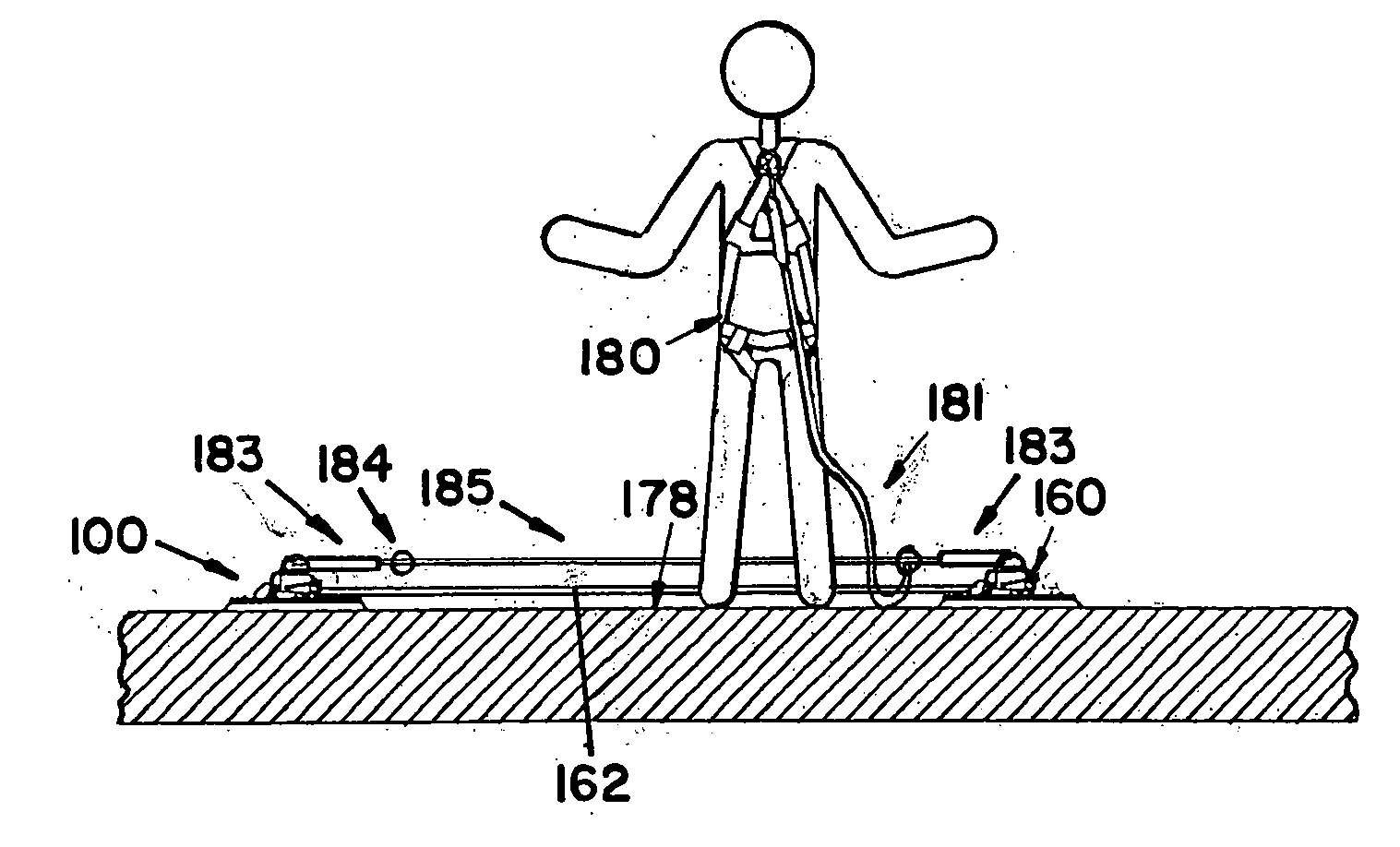
[0022] A preferred embodiment vacuum anchor constructed according to the principles of the present invention is designated by the numerals 100 and 100′ in the drawings. A preferred embodiment auxiliary vacuum anchor constructed according to the principles of the present invention is designated by the numeral 160 in the drawings.

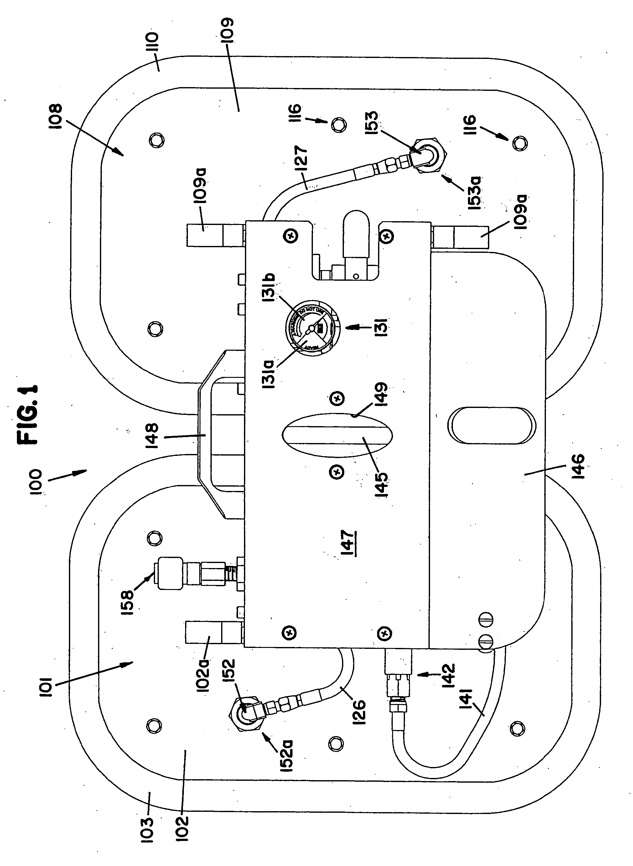
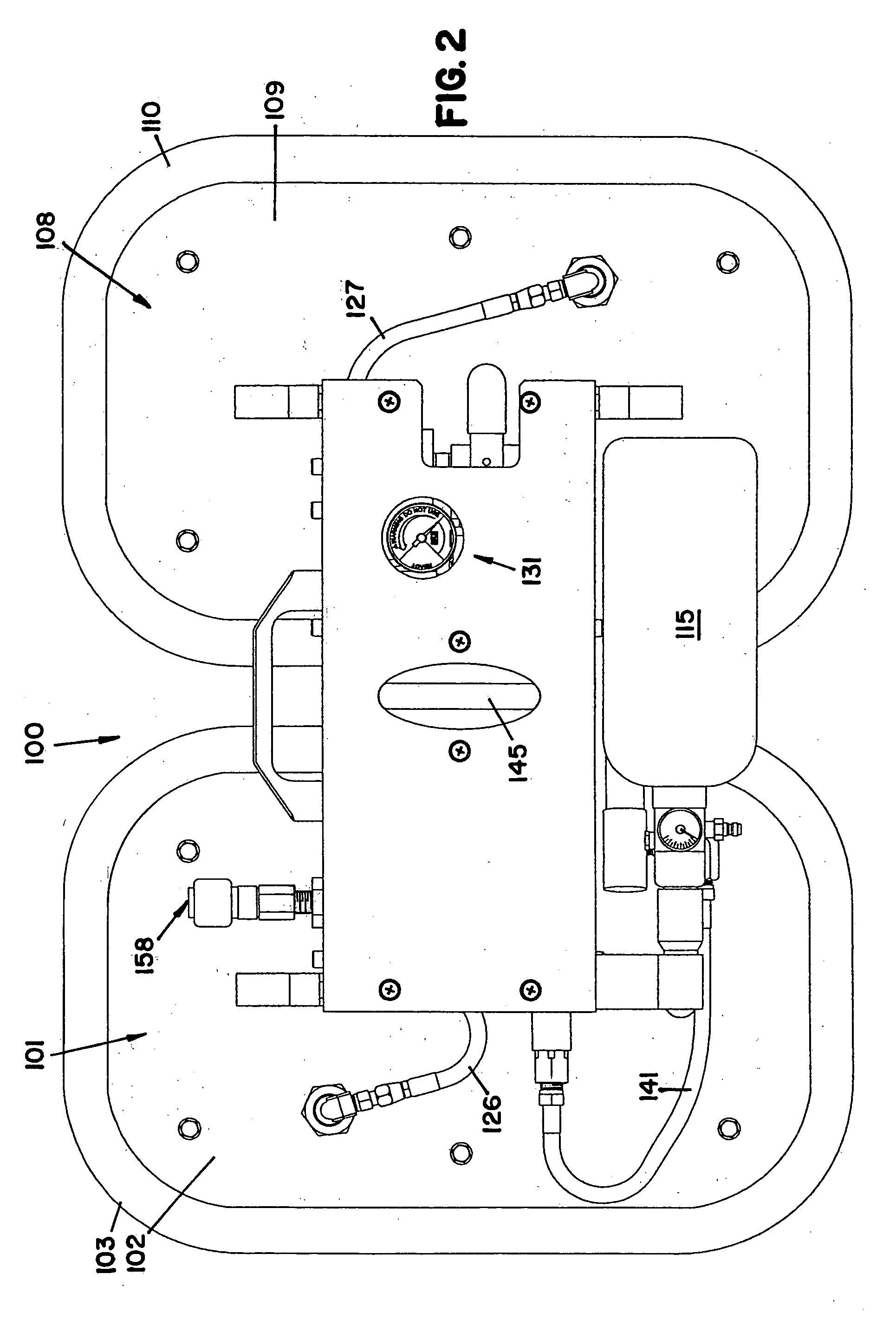
[0023] The vacuum anchor 100 includes a first anchor member 101 and a second anchor member 108. The first anchor member 101 preferably includes a first seal member 103 sandwiched between a first plate member 102 and a first bottom plate member 106 and operatively connected therebetween by fasteners 116 as shown in FIG. 11. The fasteners 116 extend through the first plate member 102, the first seal member 103, and the first bottom plate member 106 and are secured thereto. Preferably, the fasteners 116 are bolts and nuts but other suitable fasteners could be used. The first plate member 102 and the first bottom plate member 106 are each preferably rectangular ...


PUM


Abstract

In one aspect of the invention, a vacuum anchor assembly for anchoring a fall protection system to a surface of an anchorage structure comprises an anchor member having an air input connector, a venturi, and a seal member incorporated into the anchor member. The air input connector is configured and arranged to receive air from a pressurized air source. The venturi is in fluid communication with the air input connector and is configured and arranged to receive air and create a vacuum therefrom. The seal member is in fluid communication with the venturi and is configured and arranged to receive the vacuum and resulting suction and create a seal between the anchor member and the surface of the anchorage structure sufficient to operatively connect the anchor member to the surface of the anchorage structure with the vacuum and resulting suction created within the anchor member.

Description

FIELD OF THE INVENTION [0001] The present invention relates to a vacuum anchor to be used as an anchorage connector for connection of a personal fall protection system for personnel working on aircraft or other anchorage structures. BACKGROUND OF THE INVENTION [0002] Safety devices enabling personnel to perform maintenance or inspection procedures on large anchorage structures such as aircraft, storage tanks, ships, submarines, railcars, trucks, roofs, and other anchorage structures are commonly used. One type of safety device commonly used on such anchorage structures is a vacuum anchor because the vacuum anchor does not damage the surface of the anchorage structure to which it is operatively connected by suction, provided the anchorage structure meets safety standards. A remote vacuum source is typically used to supply a vacuum to the vacuum anchor and to create the suction thereby operatively connecting the vacuum anchor to the anchorage structure. The vacuum anchor depends upon ...

Claims


Application Information

Patent Timeline
IPC IPC(8): A47J45/00A62B35/00
CPCA62B35/0068
Inventor ROHLF, BRADLEY A.
Owner D B IND
Why Eureka
Try Eureka