
Plasma display apparatus and driving method thereof

a technology of plasma display and driving method, which is applied in the direction of instruments, static indicating devices, etc., can solve the problems of unstable address discharging, high temperature erroneous discharge, and so as to prevent erroneous discharge of plasma display panel temperatur

Inactive Publication Date: 2006-12-07
LG ELECTRONICS INC
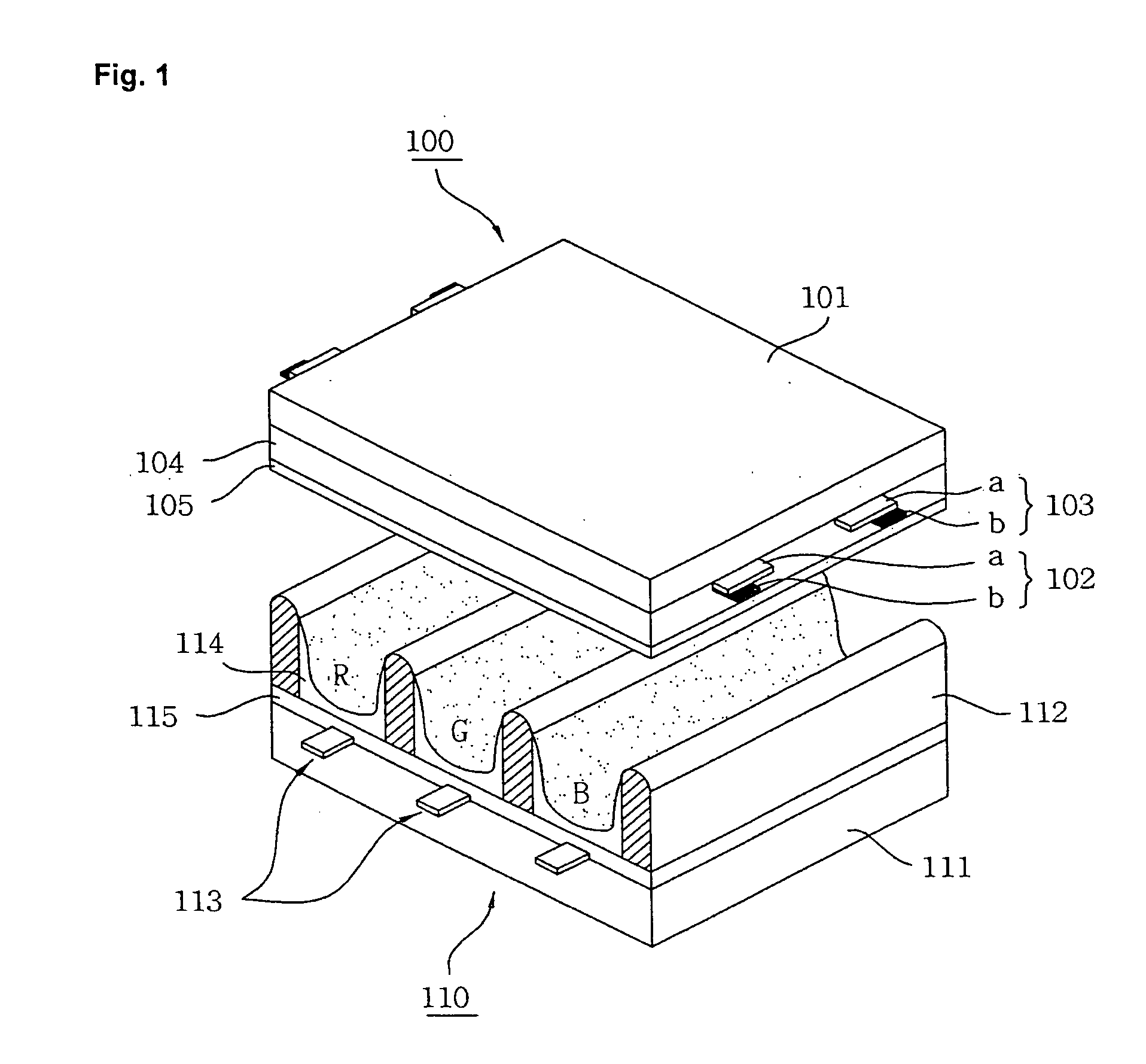
View PDF7 Cites 5 Cited by
  • Summary
  • Abstract
  • Description
  • Claims
  • Application Information

AI Technical Summary

Benefits of technology

[0039] Accordingly, the present invention has been made in view of the above problems occurring in the prior art, and it is an object of the present invention to provide a plasma display apparatus and driving method thereof, wherein erroneous discharge depending on a temperature of a plasma display panel can be prevented.
[0040] Another object of the present invention is to provide a plasma display apparatus and driving method thereof, wherein a reduction in brightness can be prohibited.
[0041] Further another object of the present invention is to provide a plasma display apparatus and driving method thereof, wherein generation of defective hot spots can be prevented.

Problems solved by technology

Accordingly, when a temperature of the panel is high, erroneous discharge is generated.
That is, high temperature erroneous discharge is generated.
This results in unstable address discharging.
This makes address discharging further unstable.
This too much increases the amount of wall charges within the discharge cells.
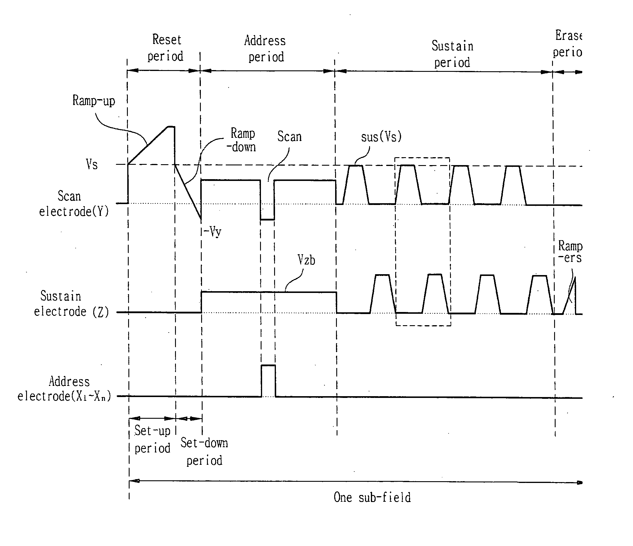
Accordingly, when a temperature of the panel is relatively low, the intensity of sustain light generated by the conventional sustain waveform of FIG. 4 excessively increases, or what is worse, low temperature erroneous discharge, such as that defective hot spots are generated, is generated.
Therefore, there is a problem in that brightness of the plasma display panel reduces.
This is because the ratio in which the wall charges and the space charges are recombined within the discharge cells reduces, as described with reference to FIG. 6, and the amount of the wall charges within the discharge cells excessively increases accordingly.
Accordingly, there is a problem in that defective hot spots are generated on the screen and the picture quality is degraded accordingly since the brightness of the plasma display panel abruptly increases.
Therefore, there is a problem in that the intensity of sustain light generated by the subsequent sustain waveform becomes weak or what is worse, sustain discharge is not generated.
Consequently, the picture quality of the plasma display panel is degraded.

Method used


Image

  • Plasma display apparatus and driving method thereof
  • Plasma display apparatus and driving method thereof
  • Plasma display apparatus and driving method thereof

Examples


first embodiment

[0066]FIG. 8 shows the construction of a plasma display apparatus according to a first embodiment of the present invention.

[0067] Referring to FIG. 8, the plasma display apparatus according to a first embodiment of the present invention includes a plasma display panel 800, a data driving unit 810, a scan driving unit 820, a sustain driving unit 830 and a sustain waveform controller 840.

[0068] The plasma display panel 800 has a front panel (not shown) and a rear panel (not shown) combined together with a predetermined distance therebetween. A plurality of sustain electrode pairs, each having a number of electrodes such as scan electrodes Y1 to Yn and a sustain electrode Z, is formed in the front panel. Further, address electrodes X1 to Xm are formed in the rear panel in such a way as to cross the sustain electrode pairs.

[0069] The data driving unit 810 is supplied with image data, which are inversely corrected and error diffused by means of an inverse gamma correction circuit, an ...

second embodiment

[0121]FIG. 14 shows the construction of a plasma display apparatus according to a second embodiment of the present invention.

[0122] Referring to FIG. 14, the plasma display apparatus according to a first embodiment of the present invention includes a plasma display panel 1400, a data driving unit 1410, a scan driving unit 1420, a sustain driving unit 1430 and a sustain waveform controller 1440.

[0123] In this case, the constituent elements of the plasma display apparatus according to a second embodiment of the present invention are the same as those of the plasma display apparatus according to the first embodiment of the present invention shown in FIG. 8, but have a different operational characteristic from those of the plasma display apparatus according to a first embodiment of the present invention. More particularly, the sustain waveform controller 1440 having a significantly different operational characteristic from that of the first embodiment of the present invention has the ...


PUM


Abstract

The present invention relates to a plasma display apparatus, and more particularly, to a plasma display apparatus and driving method thereof, wherein a sustain waveform can be improved. According to the present invention, the plasma display apparatus includes a plasma display panel comprising a plurality of sustain electrode pairs wherein each of the sustain electrode pairs has a scan electrode and a sustain electrode, and a sustain waveform controller for controlling a rising time or a falling time of sustain waveforms supplied to at least one of the sustain electrode pairs according to a temperature of the plasma display panel. The sustain waveform controller controls a time corresponding to a time point at which a sustain discharge is generated, of the rising time and the falling time. The present invention improves a plasma display apparatus and driving method thereof. Accordingly, there is an effect in that erroneous discharge depending on a temperature of a plasma display panel can be prevented.

Description

CROSS-REFERENCES TO RELATED APPLICATIONS [0001] This Nonprovisional application claims priority under 35 U.S.C. § 119(a) on Patent Application No. 10-2005-0048590 filed in Korea on Jun. 7, 2005 the entire contents of which are hereby incorporated by reference. BACKGROUND OF THE INVENTION [0002] 1. Field of the Invention [0003] The present invention relates to a plasma display apparatus, and more particularly, to a plasma display apparatus and driving method thereof, wherein a sustain waveform can be improved. [0004] 2. Background of the Related Art [0005] Generally, in a plasma display panel, a barrier rib formed between a front panel and a rear panel forms one unit cell. Each cell is filled with a main discharge gas such as neon (Ne), helium (He) or a mixed gas (Ne+He) of Ne and He, and an inert gas containing a small amount of xenon. If the inert gas is discharged with a high frequency voltage, it generates vacuum ultraviolet rays. Phosphors formed between the barrier ribs are lig...

Claims


Application Information

Patent Timeline
Patent Type & Authority Applications(United States)
IPC IPC(8): G09G3/28G09G3/288G09G3/294
CPCG09G3/294G09G2320/046G09G2320/041G09G2310/066G09G3/296
Inventor KIM, WON JAEJUNG, KYOUNG JINLEE, SUNG IM
Owner LG ELECTRONICS INC
Learn More