Method and apparatus for designing iris biometric systems for use in minimally constrained settings

a biometric system and minimally constrained technology, applied in the field of biometric techniques, can solve the problems of limited use of iris-based biometrics, extensive trial and error “tuning” and limited applicability of iris biometrics in minimally constrained settings

Inactive Publication Date: 2006-12-07
SARNOFF CORP
View PDF5 Cites 71 Cited by
  • Summary
  • Abstract
  • Description
  • Claims
  • Application Information

AI Technical Summary

Problems solved by technology

However, the widespread use of iris-based biometrics has been limited by the conditions imposed by the requirement that high resolution, high contrast images of the iris be obtained.
These limitations are workable in constrained settings such as security checkpoints, bank teller machines, or information system access points, but severely limit the applicability of iris biometrics in minimally constrained settings, such as screening in airports, subway systems, or at entrances to otherwise uncontrolled buildings or facilities.
To design a system to fulfill specific design parameters for a given minimally constrained environment for the system, extensive trial and error “tuning” is required.
Such trial and error tuning is time consuming and costly.

Method used


Image

  • Method and apparatus for designing iris biometric systems for use in minimally constrained settings
  • Method and apparatus for designing iris biometric systems for use in minimally constrained settings
  • Method and apparatus for designing iris biometric systems for use in minimally constrained settings

Examples


Embodiment Construction

[0021] The invention will be primarily described within the general context of exemplary embodiment of the present invention of a method and apparatus for defining an iris biometrics system for operation in minimally constrained settings.

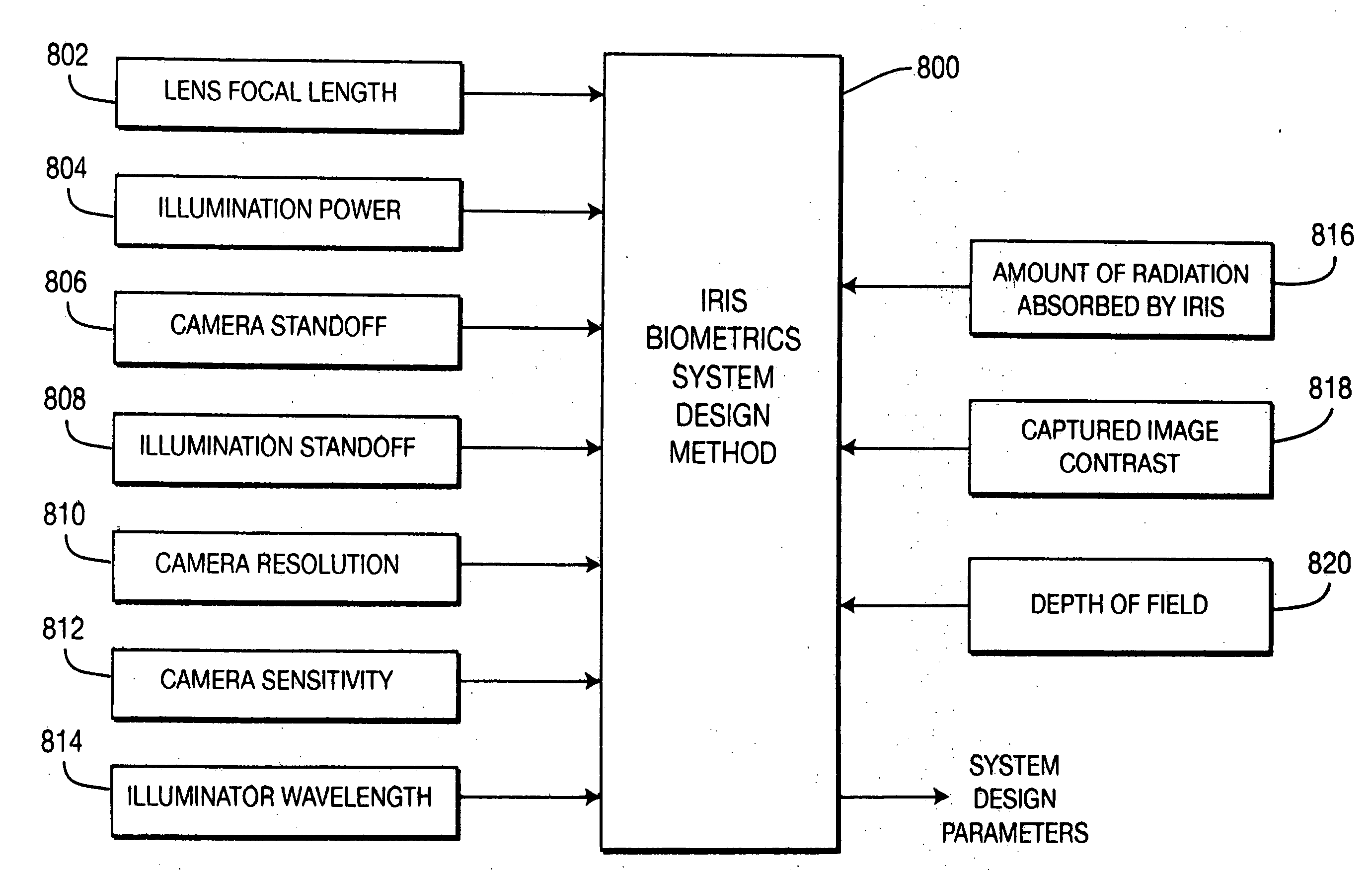
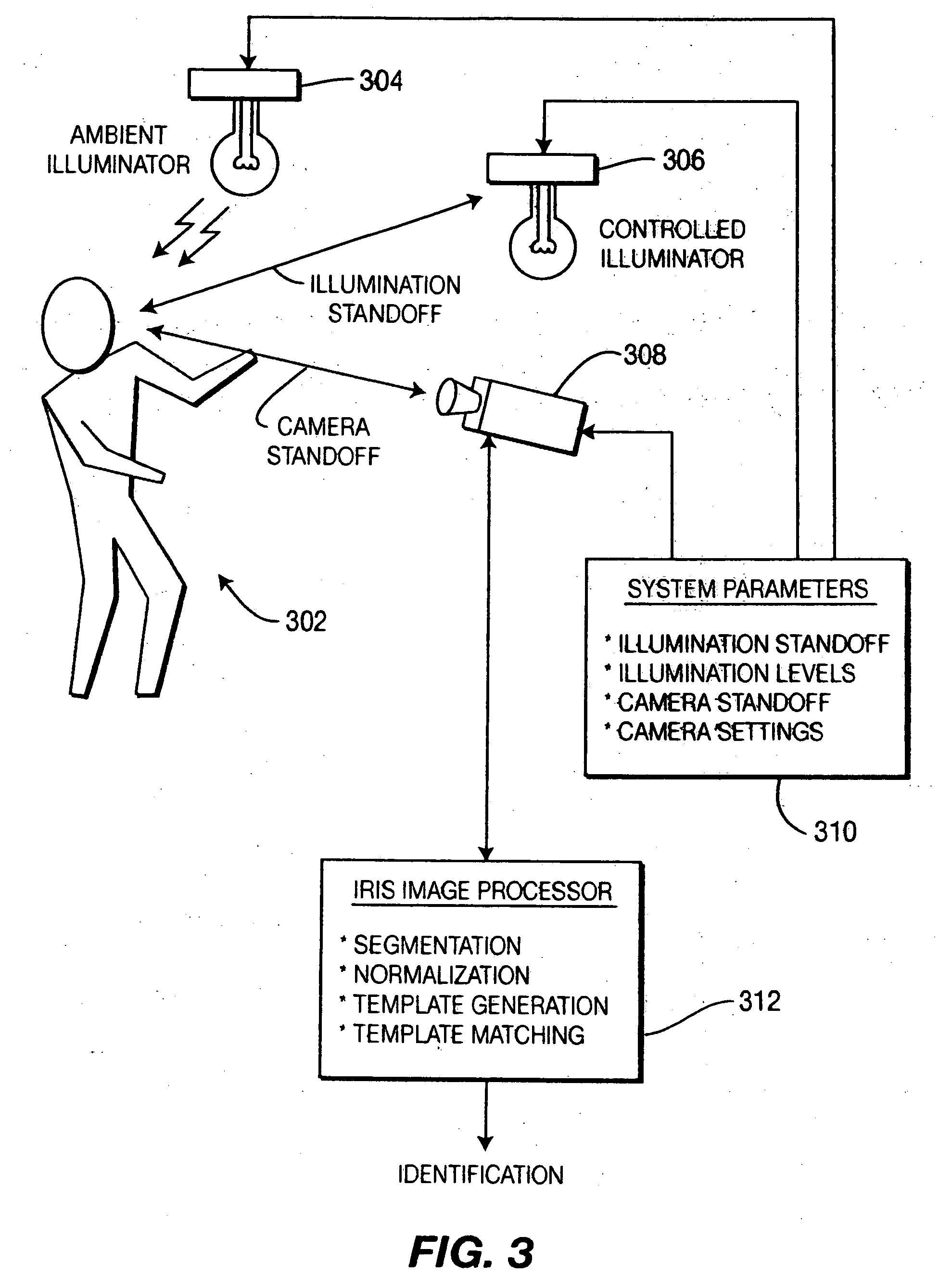
[0022] The present invention defines systems having fewer constraints on subjects than traditional methods by extending standoff distance and capture volume. The standoff distance is the distance between the image acquisition system and the subject. In some cases, there may be two standoff distances, the camera-subject distance and illumination-subject distance. The capture volume is a volume in four dimensions (i.e., space and time) within which an iris image can be captured with high probability that it will generate an acceptable iris template.

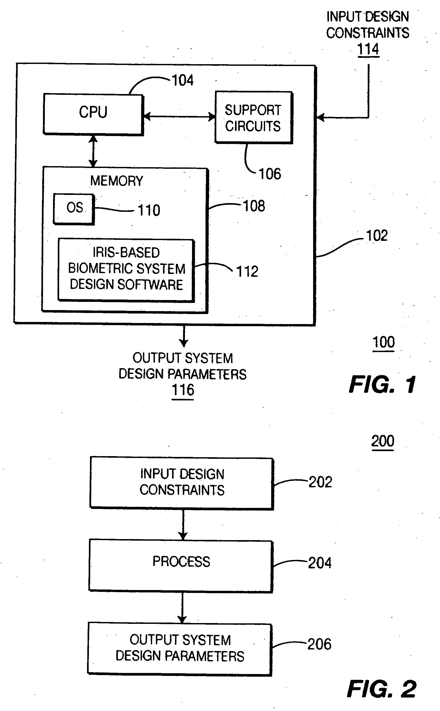
[0023] An input to the system comprises a definition of the environment in which iris biometrics are to be captured. The invention processes these environmental constraints to derive the parameters of an ...


PUM


Abstract

A method and apparatus for designing an iris biometrics system that operates in minimally constrained settings. The image acquisition system has fewer constraints on subjects than traditional methods by extending standoff distance and capture volume. The method receives design parameters and provides derived quantities that are useful in designing an image acquisition system having a specific set of performance requirements. Exemplary scenarios of minimally constrained settings are provided, such as a high volume security checkpoint, an office, an aircraft boarding bridge, a wide corridor, and an automobile.

Description

CROSS-REFERENCE TO RELATED APPLICATIONS [0001] This application claims the benefit of U.S. Provisional Application No. 60 / 687,106 filed on Jun. 3, 2005, which is incorporated herein by reference. In addition, this application is related to co-pending U.S. Application “Method and Apparatus for Providing Strobed Video Capture”, Attorney Docket No. SAR / 15245.GOVERNMENT RIGHTS IN THIS INVENTION [0002] This invention was made with U.S. government support under contract number NMA401-02-9-2001-0041. The U.S. government has certain rights in this invention.BACKGROUND OF THE INVENTION [0003] 1. Field of the Invention [0004] The invention relates generally to biometric techniques. More specifically, the invention relates to iris-based biometric techniques. [0005] 2. Description of the Related Art [0006] Iris based biometric techniques are useful for recognition, verification, or tracking of individuals. Iris based biometric methods can provide high accuracy identification and other functions...

Claims


Application Information

Patent Timeline
Patent Type & Authority Applications(United States)
IPC IPC(8): G06K9/00
CPCG06K9/6253G06K9/00604G06V40/19G06V10/945G06F18/40
Inventor AMANTEA, ROBERTBERGEN, JAMES R.LOIACONO, DOMINICKMATEY, JAMES R.NARODITSKY, OLEGTINKER, MICHAELZAPPIA, THOMAS
Owner SARNOFF CORP
Why Eureka
Try Eureka