Mounting device for a capacitor

a technology for mounting devices and capacitors, which is applied in the direction of electrical apparatus construction details, electrical discharge lamps, and support structure mounting, etc., can solve the problems of providing a self-centering of the capacitor, insufficient mounting on the possible connector elements, and high production costs of the above-cited non-standard capacitors, so as to achieve stable and reliable installation or mounting, the effect of reliably holding the capacitor

Inactive Publication Date: 2006-12-07
AIC EURO ELEKTRONISCHE BAUTEILE
View PDF7 Cites 11 Cited by
  • Summary
  • Abstract
  • Description
  • Claims
  • Application Information

AI Technical Summary

Benefits of technology

[0011] It is an object of the present invention to overcome the aforementioned disadvantages and to create a mounting device that securely and reliably holds a capacitor, ensures stable and reliable installation or mounting of the capacitor on a possible connector element, and, in addition, allows self-centering of the capacitor.

Problems solved by technology

A disadvantage of the above mentioned examples is their inadequate mounting on possible connector elements, since, for example, only a screw collar ring is provided, which does not satisfy requirements with respect to stability when mounted on a vertical wall, from which the capacitor projects horizontally.
Moreover, some of the above cited non-standard capacitors are expensive to produce.
In addition, known mounting devices do not provide a self-centering of the capacitor, so that they can be aligned and centered only with difficulty in locations which are difficult to access.

Method used


Image

  • Mounting device for a capacitor
  • Mounting device for a capacitor
  • Mounting device for a capacitor

Examples


Embodiment Construction

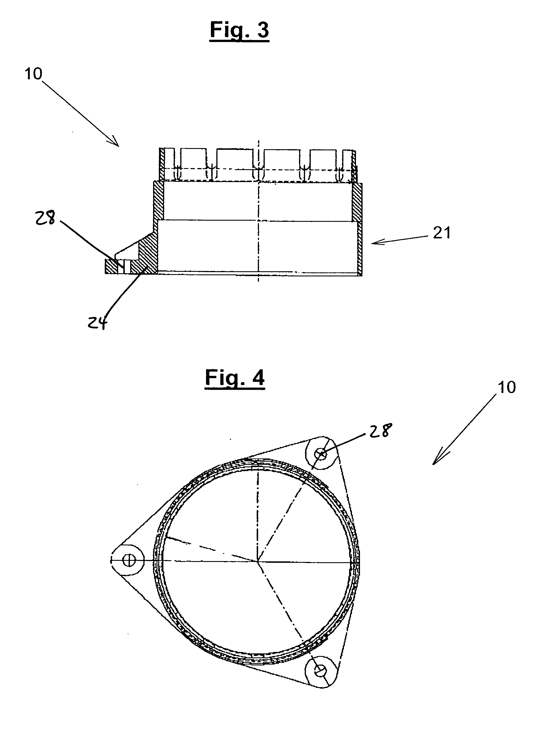
[0042]FIG. 1 shows a cross-sectional side view of a mounting device 10. The mounting device 10 has an essentially ring-shaped design with a hollow body 20 defining a through-hole 30 that penetrates the body 20 along a longitudinal axis A. The through-hole 30 is formed by several adjoining cylindrical through-hole portions having different diameters. Accordingly, the body 20 has a corresponding number of regions. In the preferred embodiment of FIG. 1, the body 20 has three regions, a lower region 21, a middle region 22, and an upper region 23. The lower through-hole portion in the lower region 21 has the largest diameter of all through-hole portions. This diameter is somewhat larger than the outside diameter of a capacitor, so that the capacitor can be mounted in the mounting device 10 with some clearance. The lower region 21 has a base 24. Through-holes 28 are provided for fastening to the connector element 60 by means of, for example, screws 70 or other fastening elements. A reinfo...


PUM


Abstract

A mounting device for mounting a capacitor on a connector element includes a hollow body defining a continuous through-hole that axially penetrates the body for receiving and mounting the capacitor. The body has a lower region defining a lower through-hole portion with a dimension. The body further has a middle region defining a middle through-hole portion with a dimension that is smaller than the first through-hole dimension. Therefore, the middle region and the lower region define a first inner shoulder between them. The body further has an upper region defining an upper through-hole portion with a dimension that is smaller than the second through-hole dimension. The upper region and the middle region define a second inner between them.

Description

BACKGROUND OF THE INVENTION [0001] 1. Field of the Invention [0002] The present invention relates to a mounting device having a hollow body with a continuous through-hole that axially penetrates the body for mounting a capacitor on a connector element, and to a mount-capacitor assembly including such a mounting device and an electrolytic capacitor inserted in the mounting device, the capacitor having a cup with a cup bottom and a circumferential outer insulation. [0003] 2. Description of the Related Art [0004] Mounting devices and assemblies of this type are used in many systems in which electrolytic capacitors are mounted on connector elements both vertically and horizontally. [0005] Various capacitors and mount-capacitor assemblies are known. [0006] DE 39 19 483 A1 and DE 38 43 652 A1 disclose basic embodiments of electrolytic capacitors. In the previously known electrolytic capacitor, the cup and the aluminum cover are welded gastight by a laser weld that extends over the outer c...

Claims


Application Information

Patent Timeline
Patent Type & Authority Applications(United States)
IPC IPC(8): H02G3/08H01L21/20
CPCH01G2/04H05K7/12H01G9/08
Inventor FRANK, BERNHARD
Owner AIC EURO ELEKTRONISCHE BAUTEILE
Why Eureka
Try Eureka