Force limiting assembly

Active Publication Date: 2006-12-07
SAINT GOBAIN PERFORMANCE PLASTICS RENCOL
View PDF12 Cites 57 Cited by
  • Summary
  • Abstract
  • Description
  • Claims
  • Application Information

AI Technical Summary

Benefits of technology

[0026] Preferably, the slip element extends the entire length of the band. The band and/or the slip element may extend partly or entirely around the perimeter of the shaft. When the slip element extend

Problems solved by technology

Because of the dimensional tolerances on the mating components and the protrusions, there is a limited range by which the tolerance ring protrusions can be compressed, giving rise to a limited range of forces available.
For applications requiring rel

Method used


Image

  • Force limiting assembly
  • Force limiting assembly
  • Force limiting assembly

Examples


first embodiment

[0059]FIG. 3 shows a force limiter according to the present invention that provides an interference fit between two mating components, e.g. mating components of a length adjustable steering wheel column assembly. One of the mating components is e.g. an outer jacket of the steering column, which essentially comprises a housing 3 having a bore 31 therein. The other of the mating component is e.g. an inner tube 4 of the steering column assembly.

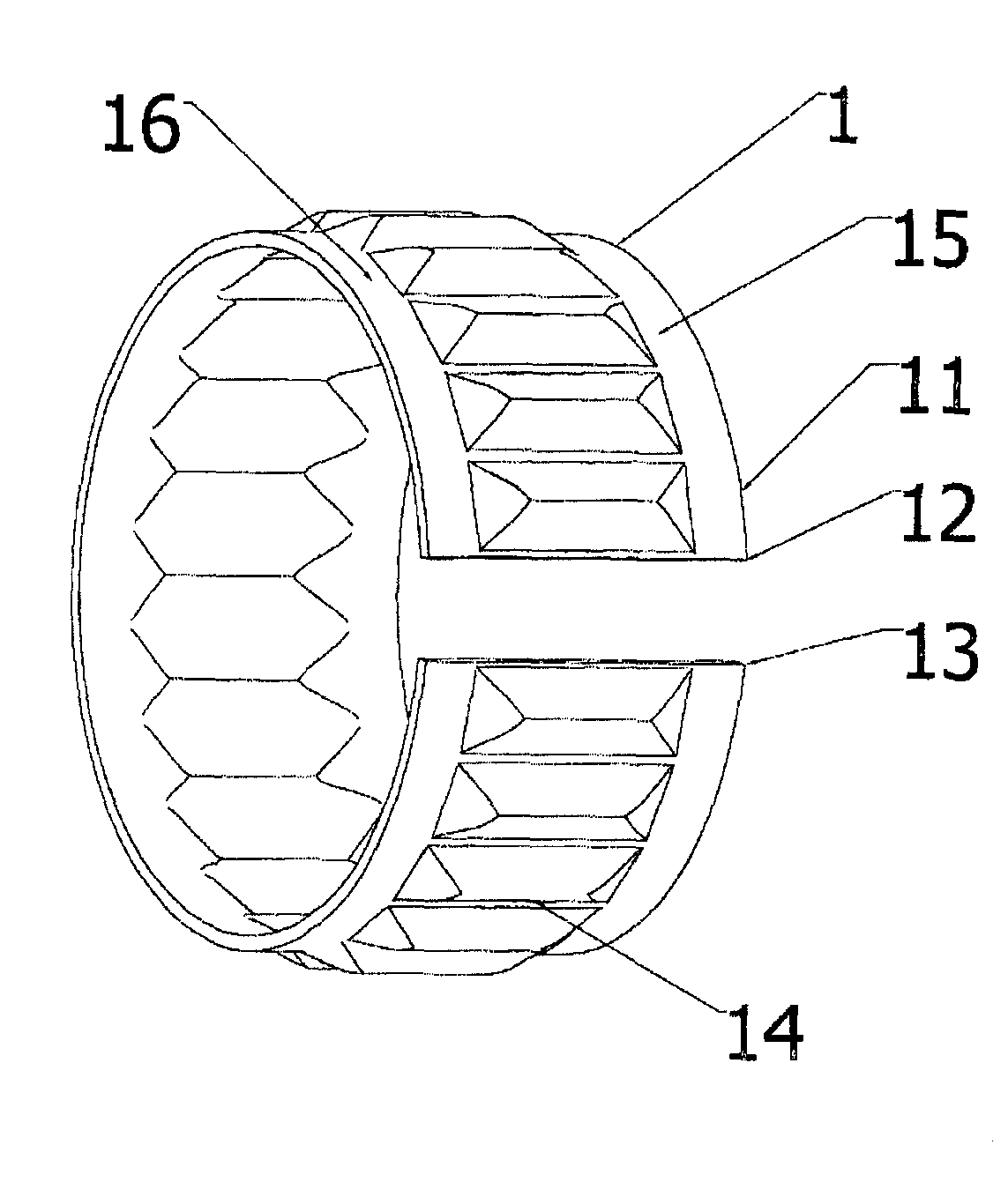
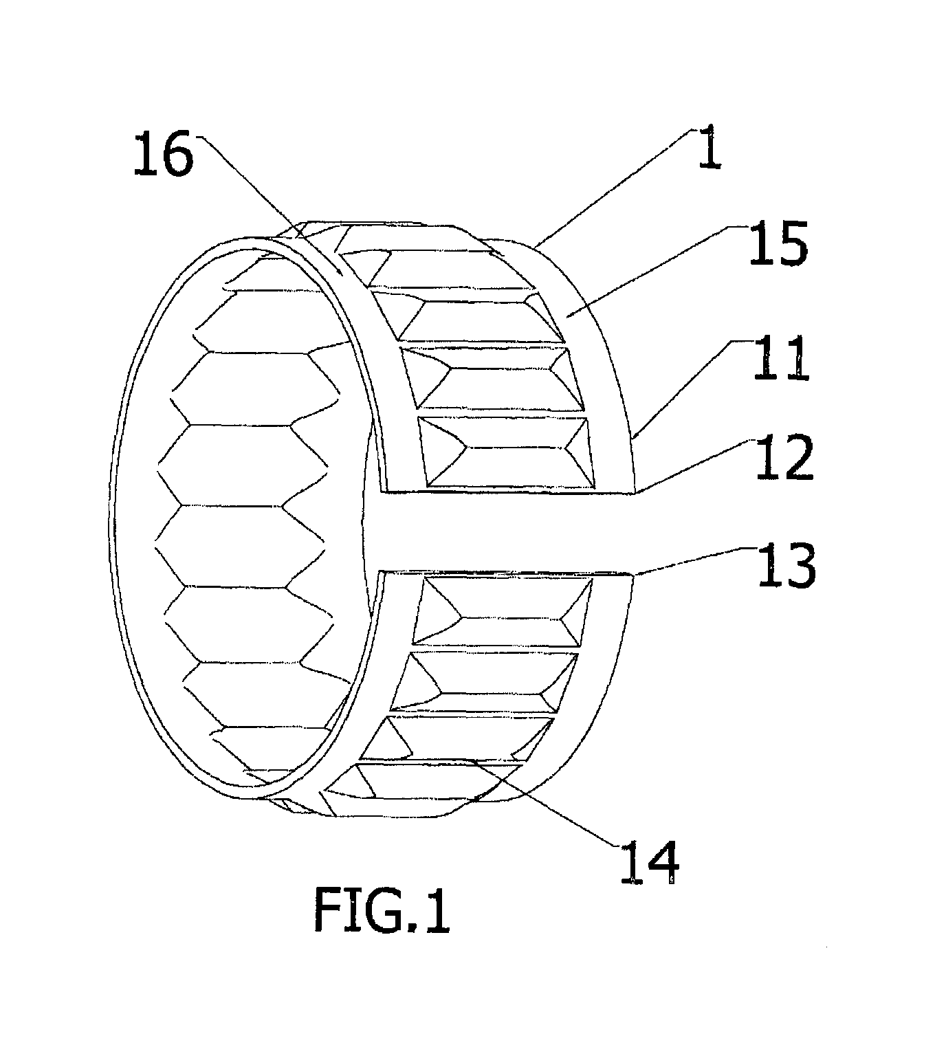
[0060] The force limiter comprises a tolerance ring 1, e.g. as described above with reference to FIG. 1, which is fitted around the slip element 2 as described above with reference to FIG. 2. Both the slip element 2 and the tolerance ring 1 extend entirely around the perimeter of the shaft 4.

[0061] The shaft 4 extends through an opening provided through the radial centre of the slip element 2. The radially inner surface of the main ring 21 of the slip element 2 is frictionally engaged with the surface of the shaft 4.

[0062]FIG. 3 in fact shows ...

third embodiment

[0075] However, in this third embodiment, the force limiter includes two axially separated tolerance rings 1 each comprising a band of resilient material 11, 12 and each having a strip of protrusions 14 extending therealong. To operate with these two bands 11, 12, the slip element 2b comprises two main ring portions 21b, 21c. The first main ring portion 21b is axially flanked on both sides by first and second flange portions 22b, 22c which project towards the first mating component (housing 3), and the second main ring portion 21c is axially flanked on both sides by said second and a third flange portion (22c and 22d respectively). The third flange portion 22d also projects towards the housing 3. The first and second flange portions 22b, 22c are spaced apart by a distance equal to the width of the first band of resilient material 11, and the second and third flange portions 22c, 22d are spaced apart by a distance equal to the width of the second band of resilient material 12, such t...


PUM


Abstract

An apparatus is shown which comprises first and second mating components with a force limiter located between them. The force limiter includes a band of resilient material, with protrusions therealong, and a slip element. The band and the slip element are secured to the first mating component with the band arranged to apply a radial force against the slip element so as to press it against the second mating component. The frictional force between slip element and the second mating component is insufficient to separate the slip element and the band from the first mating component, so any slipping that occurs between the mating components happens at the boundary of the slip element and the second mating component. A desired slip force can be obtained by choosing a slip element with an appropriate coefficient of friction, rather than by varying the dimensions of the components.

Description

CROSS-REFERENCE TO RELATED APPLICATIONS [0001] This application claims priority to Great Britain Application No. 0511494.7, filed Jun. 6, 2005, the entire contents of which are hereby incorporated by reference. BACKGROUND OF THE INVENTION [0002] 1. Field of the Invention [0003] This invention relates to force limiting assemblies such as torque limiters or tolerance rings, wherein the force limiter provides an interference fit between parts of an assembly. [0004] 2. Summary of the Prior Art [0005] Force limiters limit the maximum amount of force than can be transmitted between parts of an assembly. Commonly, a first part of the assembly has a cylindrical portion located in a cylindrical bore of a second part. The invention particularly relates to assemblies having a force limiter that provides an interference fit between a cylindrical component such as a shaft or a bearing and a housing for the shaft. [0006] Very close tolerances are required where press fits, splines, pins or keyway...

Claims


Application Information

Patent Timeline
IPC IPC(8): F16D7/02
CPCF16D7/021F16C27/02F16C29/002F16D1/0835
Inventor NEEDES, CHRISTOPHER MARKSLAYNE, ANDREW ROBERT
Owner SAINT GOBAIN PERFORMANCE PLASTICS RENCOL
Why Eureka
Try Eureka