Apparatus for assisting limb and computer program

a technology for assisting limbs and computers, applied in the field of apparatus for assisting limbs and computer programs, can solve the problems of large size, difficult to carry out synchronous control, and large inertial moment of lower limb movement, so as to reduce the load imposed on users, not only the load, but the load

Inactive Publication Date: 2006-12-07
HONDA MOTOR CO LTD
View PDF4 Cites 149 Cited by
  • Summary
  • Abstract
  • Description
  • Claims
  • Application Information

AI Technical Summary

Benefits of technology

[0017] An assist force is meant to represent a force supporting a part of the weight of the user. By providing this force, it is possible to reduce a load imposed on the user. In this connection, weight is meant to represent net weight adding up body weight, clothing and personal effects, which should be supported by lower limbs of the user when he does not use an apparatus for assisting limb.
[0018] In this way, it is possible to provide the apparatus for assisting limb, which is able to reduce not only restriction but also a load applied to the lower limb.
[0019] It is still another aspect of the present invention to provide an apparatus for assisting limb, in which the controller terminates driving of the knee joint actuator when the foot detector detects a lifted phase.
[0020] It is possible to prevent the apparatus described above from obstructing a lifted lower limb of the user.

Problems solved by technology

However, the walk-assisting device described in the patent document 1 has a problem that because the device has supporting members which tightly restrict a whole lower limb of a user, there is a great inertial moment resulting from movement of the lower limb.
If a great inertial moment occurs, it may be possibly difficult to carry out synchronous control due to response delay of the supporting members.
If an actuator having sufficient capacity is adopted for a joint driving unit so as to cancel an adverse effect due to a great inertial moment, the joint driving unit results in a large-size one, which consumes a great amount of power.
In addition, a great inertial moment leads to degraded feeling and fatigue of a user wearing a walk-assisting device.

Method used


Image

  • Apparatus for assisting limb and computer program
  • Apparatus for assisting limb and computer program
  • Apparatus for assisting limb and computer program

Examples


first embodiment

I. First Embodiment

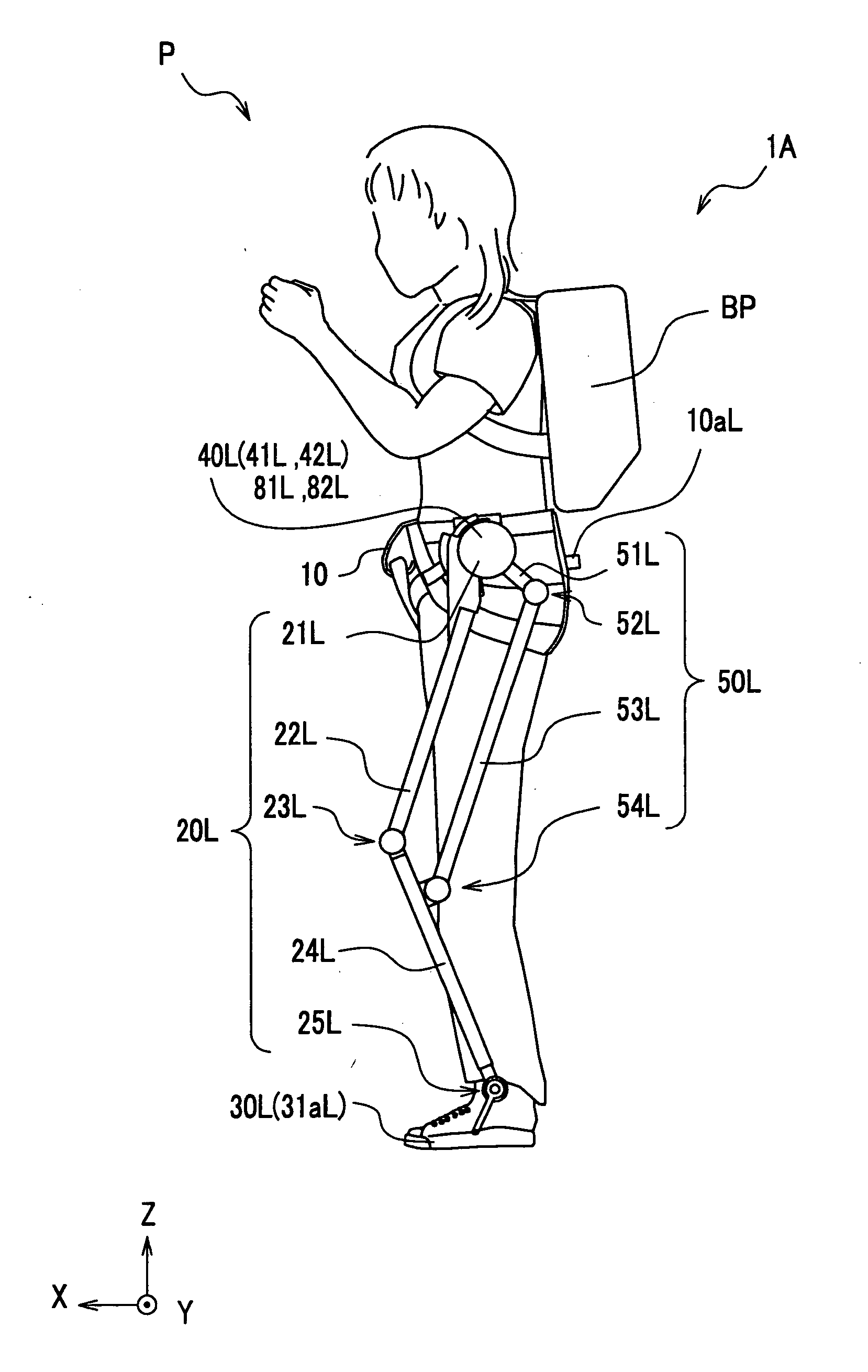
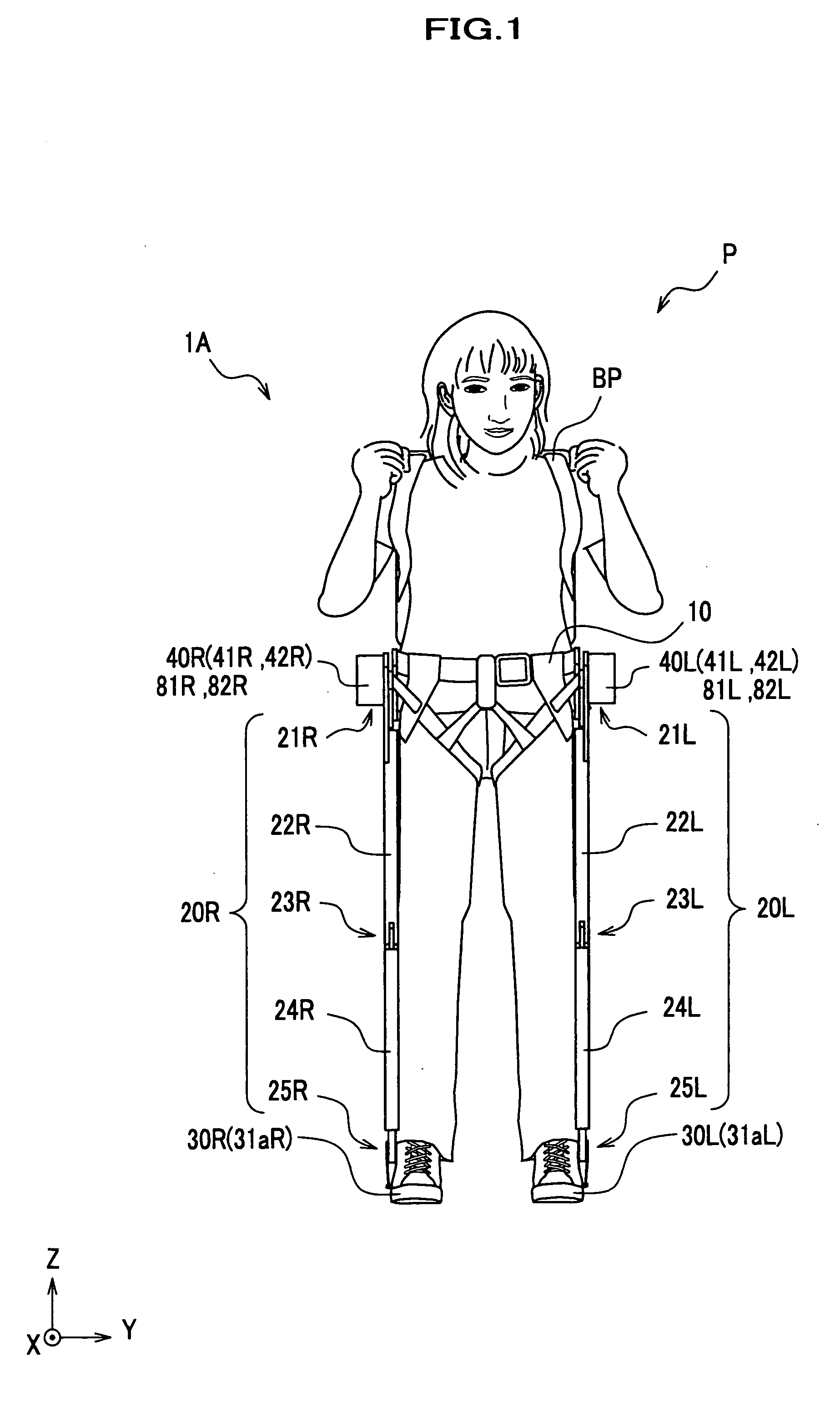
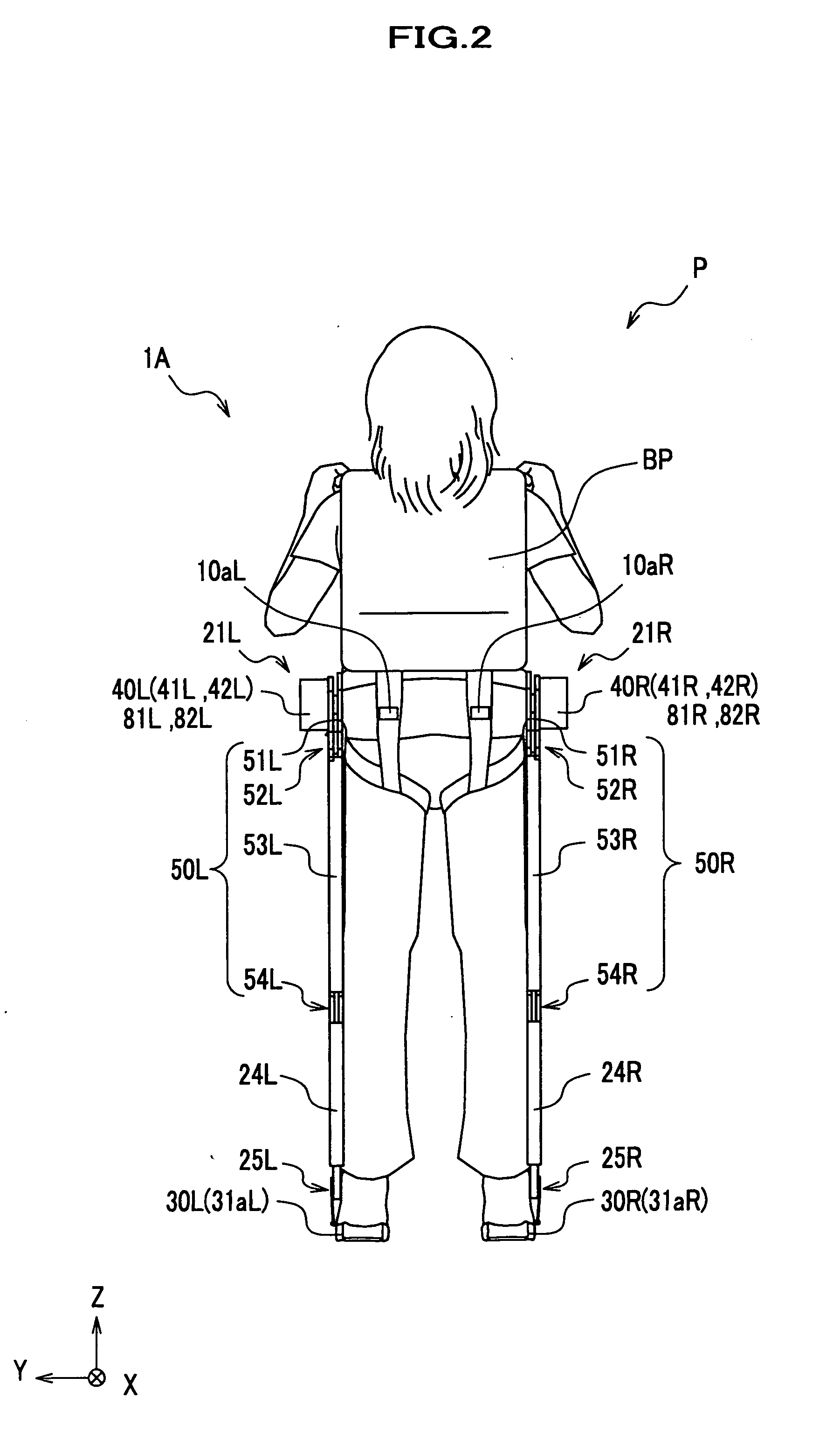
[0066] Description is given of an apparatus for assisting limb according to a first embodiment of the present invention. In FIG. 7 an ankle joint unit is not shown. FIG. 1 to FIG. 4 illustrate a user P who wears an apparatus 1A for assisting limb. For convenience of explanation, wires connecting actuators, sensors, controllers and batteries are not shown.

[0067] As shown in FIG. 1 to FIG. 4, the apparatus 1A for assisting limb (also referred to as “apparatus for assisting lower limb”) includes a body attachment 10, links for lower limb 20L and 20R, foot attachments 30L and 30R, actuator units 40L and 40R, drive units 50L and 50R and a back pack BP.

a. Body Attachment 10

[0068] As shown in FIG. 1 to FIG. 4, the body attachment 10 (also referred to as “body trunk attachment”) is attached to a trunk of the user P.

[0069] As shown in FIG. 5, the body attachment 10 includes a waist belt 11, upper leg belts 12L and 12R, actuator mounting members 13L and 13R, reinforceme...

second embodiment

II. Second Embodiment

[0231] Description is given of an apparatus for assisting limb according to a second embodiment of the present invention, focusing on differences with respect to an apparatus 1A for assisting limb according to the first embodiment. In the following drawings which are referred to in description of embodiments, only relevant portions are schematically described, which are necessary for making a comparison with the apparatus 1A according to the first embodiment. In FIGS. 19-21, for example, a hip joint actuator 41R is omitted.

[0232] In FIGS. 19 to 22, because left and right components are identical in architecture, symbols are only given to the right components, omitting those for the left ones.

[0233] As shown in FIG. 19, an apparatus 1B for assisting limb according to the second embodiment of the present invention has a drive unit 150R instead of a drive unit 50R.

[0234] The drive unit 150R has a first pulley 151R, a second pulley 152R and an endless belt 153R. ...

third embodiment

III. Third Embodiment

[0236] Description is given of an apparatus for assisting limb according to a third embodiment of the present invention, focusing on differences with respect to an apparatus 1A for assisting limb according to the first embodiment.

[0237] As shown in FIG. 20, an apparatus 1C according to the third embodiment has not only a knee joint actuator 242R instead of a knee joint actuator 42R, but also a drive unit 250R instead of a drive unit 50R.

[0238] The drive unit 250R has a wire mounting member 251R, a knee joint actuator 242R and two wires 252R and 253R. The wire mounting member 251R, which is integrally coupled with a link for lower leg 24R, is located in an outer portion of a knee joint unit 23R. The two wires 252R and 253R are routed between the wire mounting member 251R and the knee joint actuator 242R.

[0239] The knee joint actuator 242R drives the knee joint unit 23R by pulling the wire 252R and loosening the wire 253R, or vice versa.


PUM


Abstract

An apparatus for assisting limb includes a body attachment, a link for upper leg, and a knee joint unit, a link for lower leg, a lower limb attachment, a drive unit and a knee joint actuator. The body attachment is attached to a trunk of a user. The link for upper leg is placed alongside with an upper leg of the user and coupled with the body attachment. The link for lower leg is placed alongside with a lower leg of the user and coupled with the link for the upper leg via the knee joint unit. The lower limb attachment is attached to one of the lower leg and a foot of the user, and coupled with the link for lower leg. The knee joint actuator is placed in the body attachment so as to apply rotational torque to the knee joint unit via the drive unit.

Description

BACKGROUND OF THE INVENTION [0001] The present invention relates to an apparatus for assisting limb and a computer program for executing a computer for the apparatus. [0002] Walk-assisting devices which are designed to provide an assist force required for a user in walking have been disclosed in recent years. A walk-assisting device is typically used by a person who has difficulty in walking by himself, such as one lost muscle strength or suffering from leg injury. In addition, it is anticipated that a walk-assisting device will be applied to exercise and amusement, aiming at improvement in muscle strength and walking posture. [0003] A patent document 1 discloses a walk-assisting device which is attached to a lower limb of a user and has joint actuators (actuator: a combination of an electric motor and reduction gears), which are placed coaxially with a hip joint, a knee joint and an ankle joint of the user, respectively, so as to rotate them, so that the walk-assisting device provi...

Claims


Application Information

Patent Timeline
Patent Type & Authority Applications(United States)
IPC IPC(8): A61H1/02
CPCA61F5/0102A61H2201/5069A61H2201/5092A61H2201/14A61H1/0266A61H1/0277A61H1/0285A61H2201/1616A61H2201/501A61H1/0255A61H1/0262A61H3/00B25J9/0006A61H2201/0192A61H2201/1215A61H2201/163A61H2201/1642A61H2201/165A61H2201/1652A61H2201/1676A61H2201/5007A61H2201/5061A61F2002/7635
Inventor ASHIHARA, JUNHIKI, YUTAKA
Owner HONDA MOTOR CO LTD
Why Eureka
Try Eureka