Pulley structure

a technology of a belt and a belt body, which is applied in the direction of slip couplings, hoisting equipment, couplings, etc., can solve the problems of belt slippage, belt belt or belt tension change, and the belt may be prone to be lowered for a long tim

Active Publication Date: 2015-07-02
MITSUBOSHI BELTING LTD
View PDF3 Cites 14 Cited by
  • Summary
  • Abstract
  • Description
  • Claims
  • Application Information

AI Technical Summary

Benefits of technology

[0007]However, in the pulley structure disclosed in Patent Document 1, there is a problem in that since a torsional torque increases further as the torsional angle of the coil

Problems solved by technology

The slip of the belt or an excessive change in the tension of the belt is one of causes of the occurrence of an abnormal sound or lifetime depression of the belt.
In particular, since a power generating shaft of the alternator has a large moment of inertia, a slip of the b

Method used


Image

  • Pulley structure
  • Pulley structure
  • Pulley structure

Examples


first embodiment

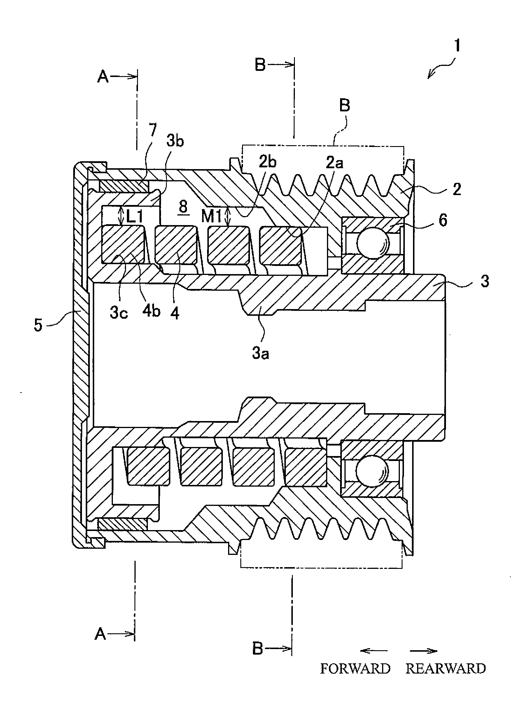
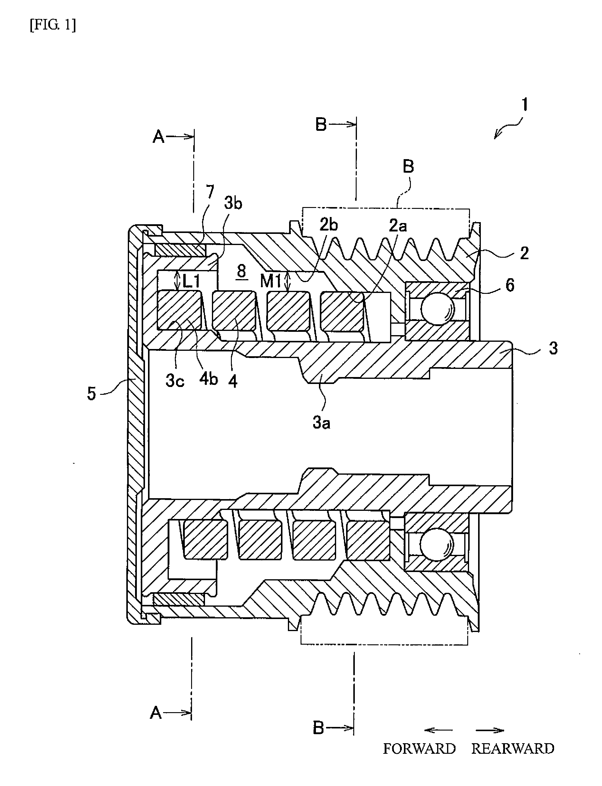
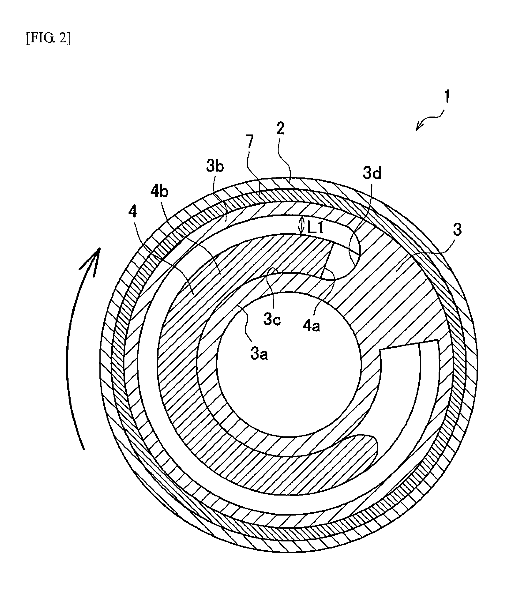
[0079]Hereafter, a pulley structure 1 of a first embodiment of the present invention will be described.

[0080]The pulley structure 1 of this embodiment is installed on a drive shaft of an alternator in an auxiliary unit drive system (not illustrated) of a vehicle. The auxiliary unit drive system has a configuration in which a belt is stretched over a drive pulley connected to a crankshaft of an engine and a driven pulley that drives an auxiliary unit such as an alternator. The rotation of the crankshaft is transmitted to the driven pulley via the belt, so that the auxiliary unit such as an alternator is driven. The rotating speed of the crankshaft changes due to a combustion event of the engine, and the speed of the belt also changes in association with this change.

[0081]As illustrated in FIG. 1 to FIG. 3, the pulley structure 1 of this embodiment includes a first rotatable body 2 having a substantially cylindrical shape, over which a belt B is stretched; a second rotatable body 3 ha...

second embodiment

[0113]Subsequently, a pulley structure 101 of a second embodiment of the present invention will be described. The same reference signs are assigned to components having the same configurations as the first embodiment and descriptions thereof will be appropriately omitted.

[0114]Similar to the first embodiment, the pulley structure 101 of this embodiment is installed on the drive shaft of an alternator of an auxiliary unit drive system. As illustrated in FIG. 5 to FIG. 7, the pulley structure 101 includes a first rotatable body 102 having a substantially cylindrical shape, over which belt B is stretched; a second rotatable body 103 having a substantially cylindrical shape and disposed inward of the first rotatable body 102 with the same rotation axis; a torsional coil spring 104; and an end cap 5.

[0115]The first rotatable body 102 has a cylinder main body 102a over which the belt B is stretched, and an inner cylinder portion 102b which is disposed inward of the cylinder main body 102a...

third embodiment

[0137]Subsequently, a pulley structure 201 of a third embodiment of the present invention will be described. The same reference signs are assigned to components having the same configurations as the first embodiment, and descriptions thereof will be appropriately omitted.

[0138]Similar to the first embodiment, the pulley structure 201 of this embodiment is installed on the drive shaft of an alternator of an auxiliary unit drive system. As illustrated in FIG. 8 to FIG. 10, the pulley structure 201 includes a first rotatable body 202 having a substantially cylindrical shape, over which belt B is stretched; a second rotatable body 203 having a substantially cylindrical shape and disposed inward of the first rotatable body 202 with the same rotation axis; a torsional coil spring 204; and an end cap 5.

[0139]The first rotatable body 202 has a cylinder main body 202a over which the belt B is stretched, and an inner cylinder portion 202b which is disposed inward of a front end portion of the...


PUM


Abstract

The present invention relates to a pulley structure containing a first rotatable body, a second rotatable body and a torsional coil spring, in which the torsional coil spring has one end region, the outer circumferential surface of which is in contact with one rotatable body due to the self elastic restoring force when the pulley structure is in a stopped state, the other end region, the inner circumferential surface of which is in contact with the other rotatable body when the pulley structure is in the stopped state, and a middle region, and in which when the torsional coil spring is twisted in the diameter increasing direction, the inner circumferential surface of at least a circumferential portion of the other end region of the torsional coil spring separates from the other rotatable body.

Description

TECHNICAL FIELD[0001]The present invention relates to a pulley structure with a coil spring.BACKGROUND ART[0002]In an auxiliary unit drive system that drives, by the power of an engine for a vehicle, an auxiliary unit such as an alternator, a belt is stretched over a pulley connected to a drive shaft of the auxiliary unit such as the alternator and a pulley connected to a crankshaft of the engine, and torque of the engine is transmitted to the auxiliary unit via the belt. Typically, the rotating speed of the crankshaft of the engine changes due to a power stroke of the engine or the like, and the travelling speed of the belt also changes. For this reason, a slip may occur between the pulley connected to the drive shaft of the auxiliary unit and the belt, or the tension of the belt may change considerably. The slip of the belt or an excessive change in the tension of the belt is one of causes of the occurrence of an abnormal sound or lifetime depression of the belt.[0003]In particula...

Claims


Application Information

Patent Timeline
IPC IPC(8): F16D41/20F16H55/36F16D7/02
CPCF16D41/206F16H2055/366F16H55/36F16D7/022F16F15/1216F16D3/12F16D3/74F16D13/08F16D41/20F16F15/123F16F15/129
Inventor SHIMAMURA, HAYATODAN, RYOSUKEHARAGUCHI, MAKOTOIMAI, KATSUYA
Owner MITSUBOSHI BELTING LTD
Why Eureka
Try Eureka