Hybrid construction machine

a construction machine and hybrid technology, applied in the direction of electric propulsion mounting, jet propulsion mounting, transportation and packaging, etc., can solve the problems of affecting the durability and performance of the generator motor, affecting the stability of the supporting state, and affecting the durability of the generator motor. , to achieve the effect of reducing costs, increasing the strength of the mounting device, and facilitating assembly

Active Publication Date: 2011-03-31
KOBELCO CONSTR MASCH CO LTD
View PDF14 Cites 18 Cited by
  • Summary
  • Abstract
  • Description
  • Claims
  • Application Information

AI Technical Summary

Benefits of technology

[0023]Accordingly, it is an object of the present invention to provide a hybrid construction machine that can stably support a power unit at both sides thereof that are at substantially equal distances from the center of gravity of the power unit, and that can reduce a load exerted upon a generator motor.
[0024]According to an aspect of the present invention, there is provided a hybrid construction machine comprising an engine, a generator motor, a hydraulic pump, all of which constitute a power unit, and are connected in series, with the generator motor being disposed between the engine and the hydraulic pump and with a center of gravity of the entire power unit being positioned closer to the generator motor than a center of gravity of the engine. On this presupposition, mount devices are disposed at the engine and the generator motor, respectively, with the center of gravity of the entire power unit being disposed therebetween. In addition, the power unit is supported on a body frame of the machine by the mount devices. Therefore, it is possible to stably support the power unit with the distance between the center of gravity of the power unit and the mount device at one side and the distance between the center of gravity of the power unit and the mount device at the other side being substantially equal to each other.
[0025]This makes it possible to substantially equalize a load on the mount devices at both sides to overcome the possibility of insufficient strengths of the mount devices, and to reduce vibration.

Problems solved by technology

Therefore, the stability of a supporting state becomes extremely poor.
More specifically, since an unbalanced load acts, for example, the left mount device may have insufficient strength due to an increase in load on the left mount device 11, or vibration may tend to occur.
Consequently, a force is forcefully generated at an internal structure through a rotary shaft, thereby adversely affecting the durability and performance of the generator motor 14.

Method used


Image

  • Hybrid construction machine
  • Hybrid construction machine
  • Hybrid construction machine

Examples


Embodiment Construction

[0042]An embodiment of the present invention will be described with reference to FIGS. 1 to 4.

[0043]In the embodiment, the present invention is applied to a hybrid excavator.

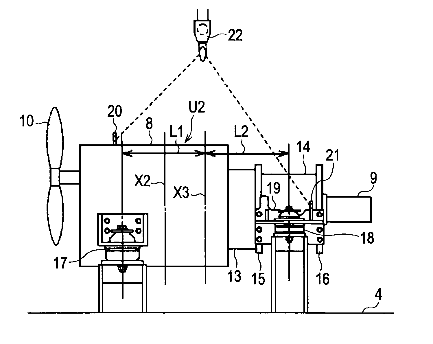
[0044]Similarly to FIG. 7, FIG. 1 shows a power unit in an engine room and a supporting structure thereof, as viewed from a back side of a machine.

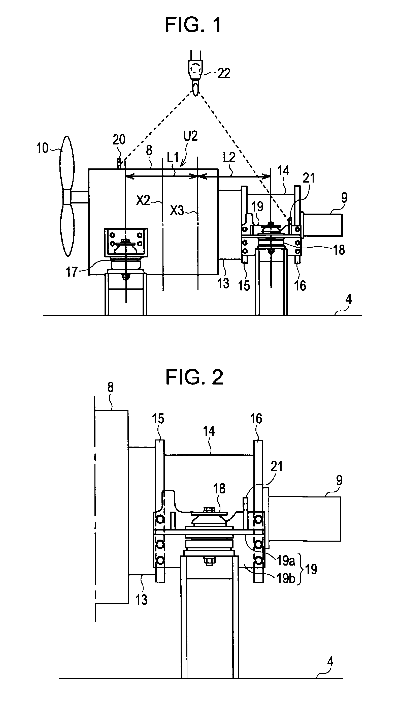
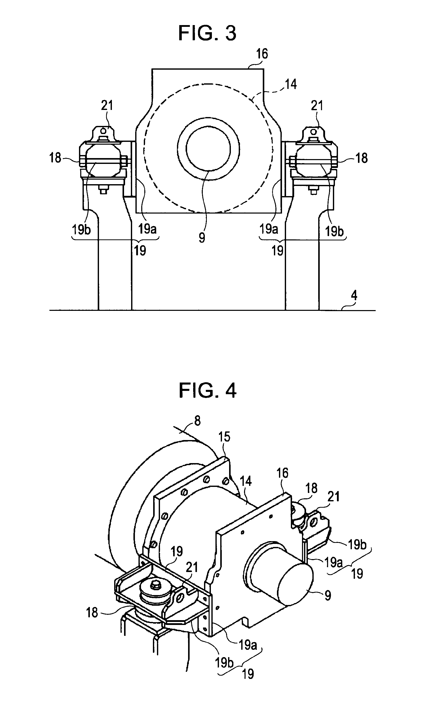
[0045]FIG. 1 shows that (I) a power unit U2 is formed by providing a generator motor 14 between an engine 8 and a hydraulic pump 9, (II) an engine-side flange 15 and a pump-side flange 16, which have the form of thick plates, are provided on the left and right of the generator motor 14, respectively, so as to project towards the outer periphery while they act as end covers; and the engine-side flange 15 is connected to a fly wheel housing 13 at the engine 8, and the pump-side flange 16 is connected to the hydraulic pump 9, and (III) a center of gravity X3 of the power unit is shifted considerably towards the hydraulic pump from the center of gravity X1 of the hydrauli...


PUM


Abstract

A hybrid construction machine includes an engine, a generator motor, and a hydraulic pump. They constitute a power unit, and are connected in series, with the generator motor being disposed between the engine and the hydraulic pump and with a center of gravity of the entire power unit being positioned closer to the generator motor than the center of gravity of the engine. A mount installation bracket is mounted at a side of each flange disposed at a corresponding side of the generator motor. A generator-motor-side mount device is mounted to the bracket.

Description

BACKGROUND OF THE INVENTION[0001]1. Field of the Invention[0002]The present invention relates to a hybrid construction machine in which a power unit is formed by connecting three devices, that is, an engine, a generator motor, and a hydraulic pump in series with each other.[0003]2. Description of the Related Art[0004]As shown in FIG. 5, in an excavator, an upper rotating structure 2, disposed on a crawler-type lower traveling structure 1, is mounted so as to be rotatable around a vertical axis that is perpendicular to the ground, and a working attachment 3 is mounted to a front portion of the upper rotating structure 2.[0005]A cabin 5, a counterweight 6, and an engine room 7 are provided at the upper rotating structure 2. The cabin 5 is provided at the left side of a front portion of an upper frame 4 serving as a base. The counterweight 6 is provided at a back end portion of the upper frame 4. The engine room 7 is provided at a back portion (forwardly of the counterweight 6) of the ...

Claims


Application Information

Patent Timeline
Patent Type & Authority Applications(United States)
IPC IPC(8): B60K5/08
CPCB60K6/12B60K6/40B60K6/48B60Y2200/25Y02T10/6282E02F9/2075Y02T10/6208Y02T10/6221E02F9/0866Y02T10/62
Inventor MANABE, TETSUNORISUGANO, TAKAO
Owner KOBELCO CONSTR MASCH CO LTD
Why Eureka
Try Eureka