Bayonet release of safety shield for needle tip

Inactive Publication Date: 2006-12-07
TYCO HEALTHCARE GRP LP
View PDF99 Cites 34 Cited by
  • Summary
  • Abstract
  • Description
  • Claims
  • Application Information

AI Technical Summary

Benefits of technology

[0007] In one aspect of the present invention, a needle assembly generally comprises a handle for manipulating the needle assembly, and a needle mounted on the handle and extending outwardly therefrom. The needle has a longitudinal axis and a sharp end. A safety shield associated with the needle can move relative to the needle between a stowed position in which the safety shield is

Problems solved by technology

However, some needle assemblies require the application of substantial force in use.
Failure to make the operation of the safety devi

Method used


Image

  • Bayonet release of safety shield for needle tip
  • Bayonet release of safety shield for needle tip
  • Bayonet release of safety shield for needle tip

Examples


Embodiment Construction

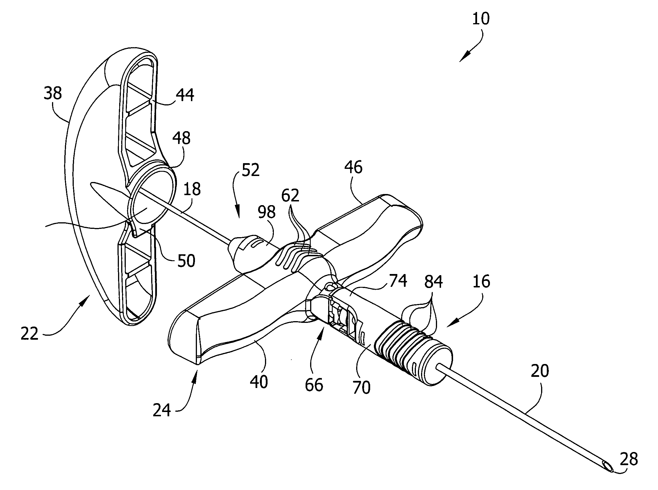
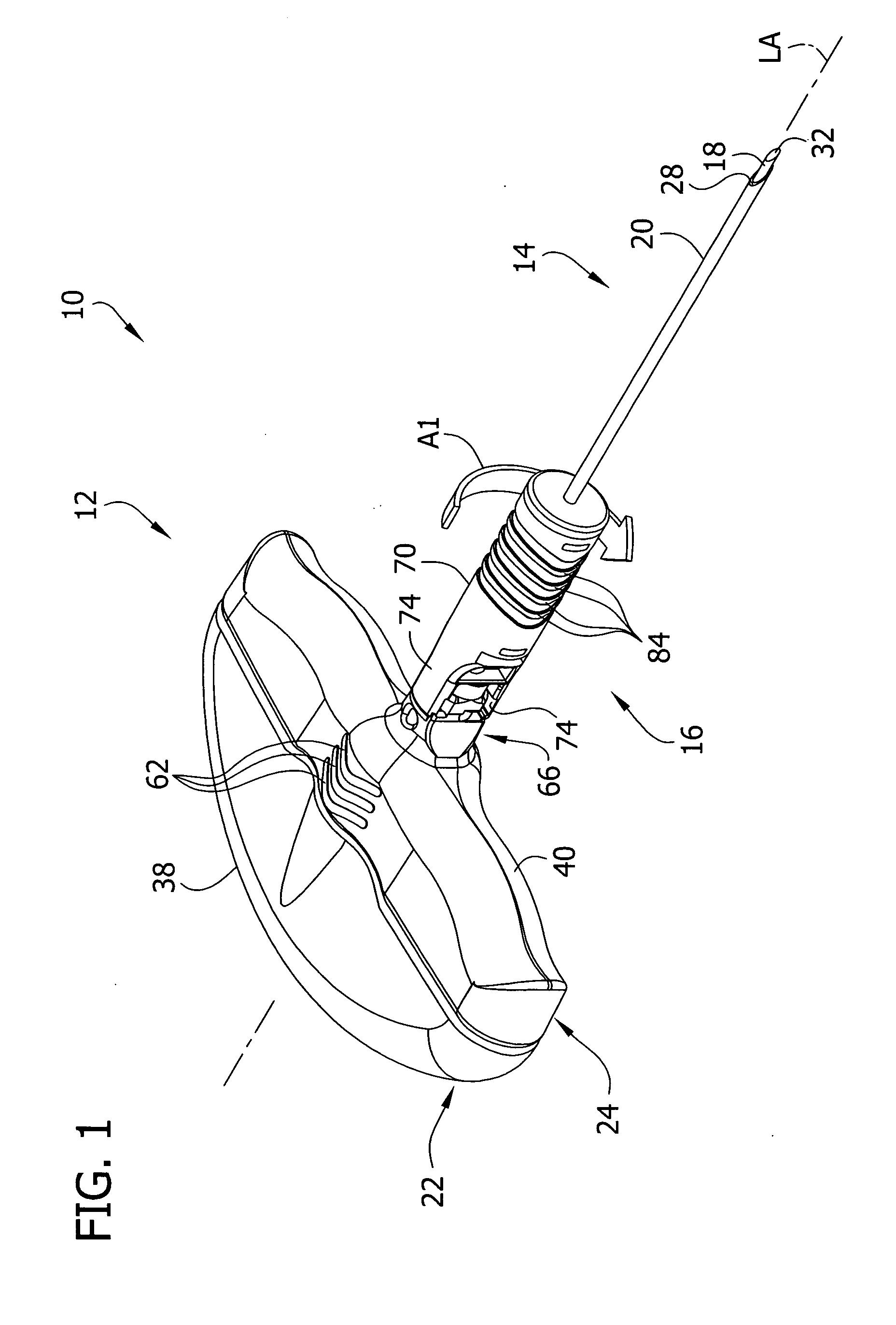
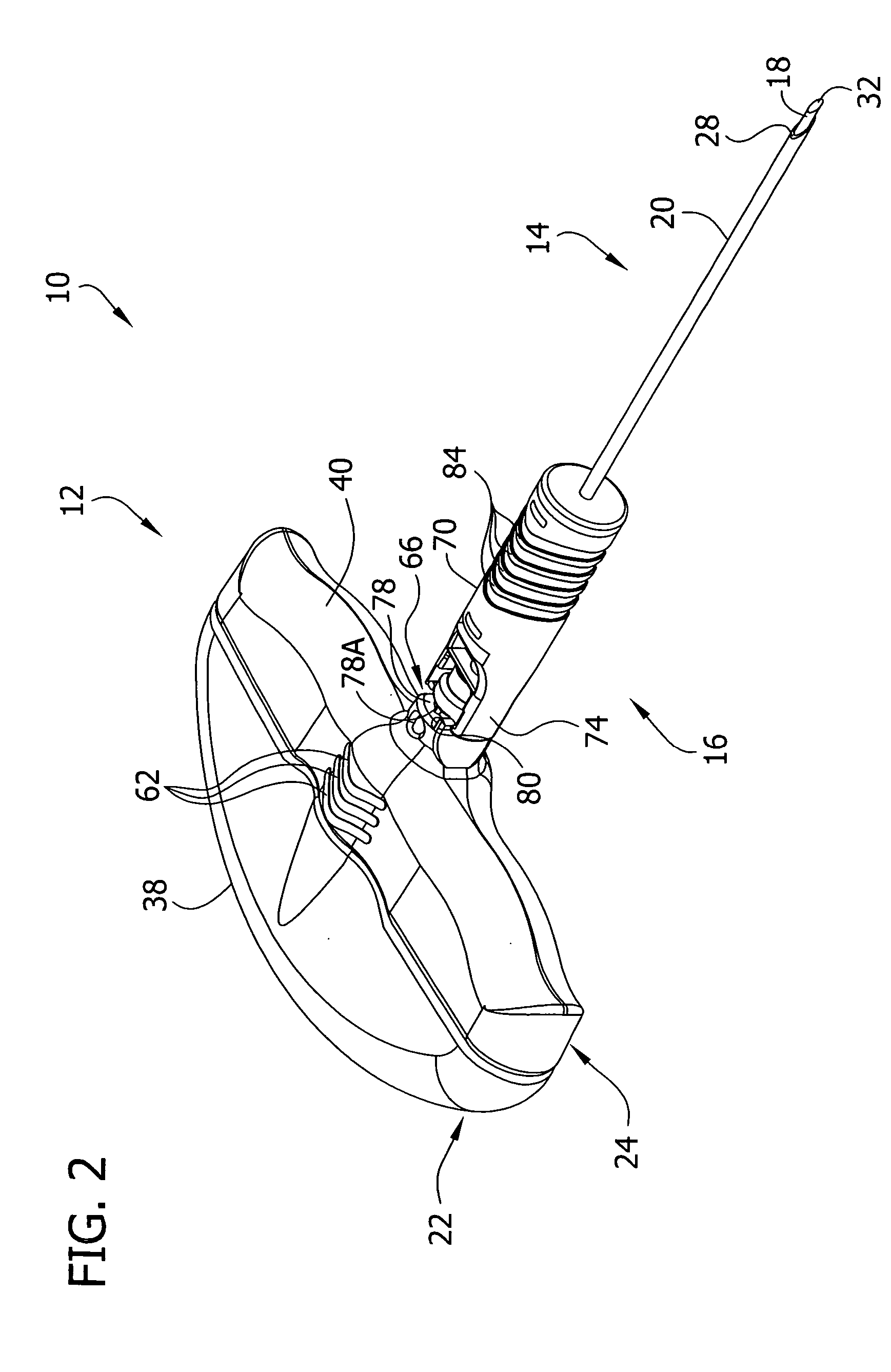
[0023] Referring now to the drawings and in particular to FIGS. 1 and 2, a medical instrument constructed according to the principles of the present invention is shown in the form of a bone needle assembly, generally indicated at 10. The bone needle assembly includes a handle 12 (broadly, “mounting structure”), a needle 14 and a cannula safety shield 16 (broadly, “an operative member”), all reference numbers indicating their subjects generally. The needle 14 includes a stylet 18 and a cannula 20 that can receive the stylet. The handle 12 includes a first or proximal handle member (indicated generally at 22) mounting the stylet 18, and a second or distal handle member (indicated generally at 24) mounting the cannula 20. It will be understood that a needle could include only a single component part, or more than two parts within the scope of the present invention. Similarly, a handle could be a single part or more than two parts. The mounting structure for the needle 14 can be other t...


PUM


Abstract

A needle assembly having a shield attached for quick release from the remainder of the needle assembly to be moved to cover the sharp tip. The shield can be disconnected by rotation of only about 90 degrees. When not needed to cover the sharp tip, the shield is held in a stowed position out of the way so as not to interfere with use of the needle assembly.

Description

CROSS REFERENCE TO RELATED APPLICATION [0001] This application includes subject matter in common with co-assigned U.S. patent application Ser. No. ______, entitled Needle Assembly with Removable Depth Stop, filed simultaneously herewith. The subject matter of this application is incorporated herein in its entirety by reference. BACKGROUND OF THE INVENTION [0002] This invention relates generally to needle assemblies and more particularly to needle assemblies that have shields to cover sharp ends of needles. [0003] Needle assemblies of the present invention have particular, although not exclusive application in the field of medicine and have needles with sharpened ends for use in piercing the skin to inject or withdraw materials as needed. The needle assembly may also be used to inject or withdraw material from an IV line so that penetration of the skin is not always undertaken. [0004] The needle is supported by some other structure that is used to manipulate the needle. The most comm...

Claims


Application Information

Patent Timeline
IPC IPC(8): A61M31/00
CPCA61B10/025A61B2019/481A61B2017/32113A61B2090/08021A61M5/162A61M25/06A61M5/32
Inventor MOOS, KIMBERLY A.SWISHER, DAVID RORKREYNOLDS, WHITNEY
Owner TYCO HEALTHCARE GRP LP
Why Eureka
Try Eureka