Method of repairing a blade member

a blade member and metal technology, applied in the direction of efficient propulsion technologies, machines/engines, manufacturing tools, etc., can solve the problems of blades being subject to damage, expensive to manufacture, maintain and repair, and sometimes experiencing damage, so as to induce compressive stresses

Inactive Publication Date: 2006-12-14
SN DETUDE & DE CONSTR DE MOTEURS DAVIATION S N E C M A
View PDF14 Cites 60 Cited by
  • Summary
  • Abstract
  • Description
  • Claims
  • Application Information

AI Technical Summary

Benefits of technology

[0013] Burnishing beneficially cold works the material of the blade member to induce compressive stresses in the repaired blade member. It is a particular feature of the present invention that the burnishing provides an effective but economical substitute for laser shock peening. These compressive stresses counteract residual stresses in the blade member structure caused by welding the replacement portion into place.

Problems solved by technology

Moreover, depending on the application, such bladed members are made from metal or special metal alloys, and can be generally expensive to manufacture, maintain, and repair.
Yet, over time and in the course of normal operation, these blades are generally subject to damage due to aging and wear.
They also occasionally experience damage due to external factors such as foreign object damage in jet engines, problems occurring during the manufacture of constituent parts or during assembly, and design flaws.
Damage may also include thermal and mechanical deformation, damage caused by vibration during operation, and damage caused by overheating during operation.
Even though physical damage to blades may be relatively localized, it is common practice to scrap an entire blade with an isolated damaged region rather than repair it.
This is of course quite expensive, especially if a significant portion of the blade is still structurally sound.
In addition, with the advent of bladed disks (which are sometimes referred to in the art as “blisks,” and sometimes also known in the art as “bladed monoblock disks”), an inability to perform local repairs becomes very costly in the face of replacing an entire blisk assembly.
In general, repair methods that contemplate separating a blade from its hub are by definition incompatible with the blisk structure.
As a result, an entire blisk may be scrapped because of damage to just a few of the blades thereon.
However, laser shock peening is relatively expensive, time consuming, technically demanding, and usually entails significant startup costs, which can make it unacceptable for some applications, as mentioned in U.S. Pat. No. 6,415,486.
The counteracting stresses induced as a result however are relatively weak.
In addition, it is known in the conventional art that brazing and other filling methods of repair sometimes suffer because the filler material does not match the mechanical characteristics of the original constituent metal.
In addition, this approach means that the process of repair is dependent on the nature of the damage, such that it becomes difficult to establish a readily reproducible repair protocol.

Method used


Image

  • Method of repairing a blade member
  • Method of repairing a blade member
  • Method of repairing a blade member

Examples


Embodiment Construction

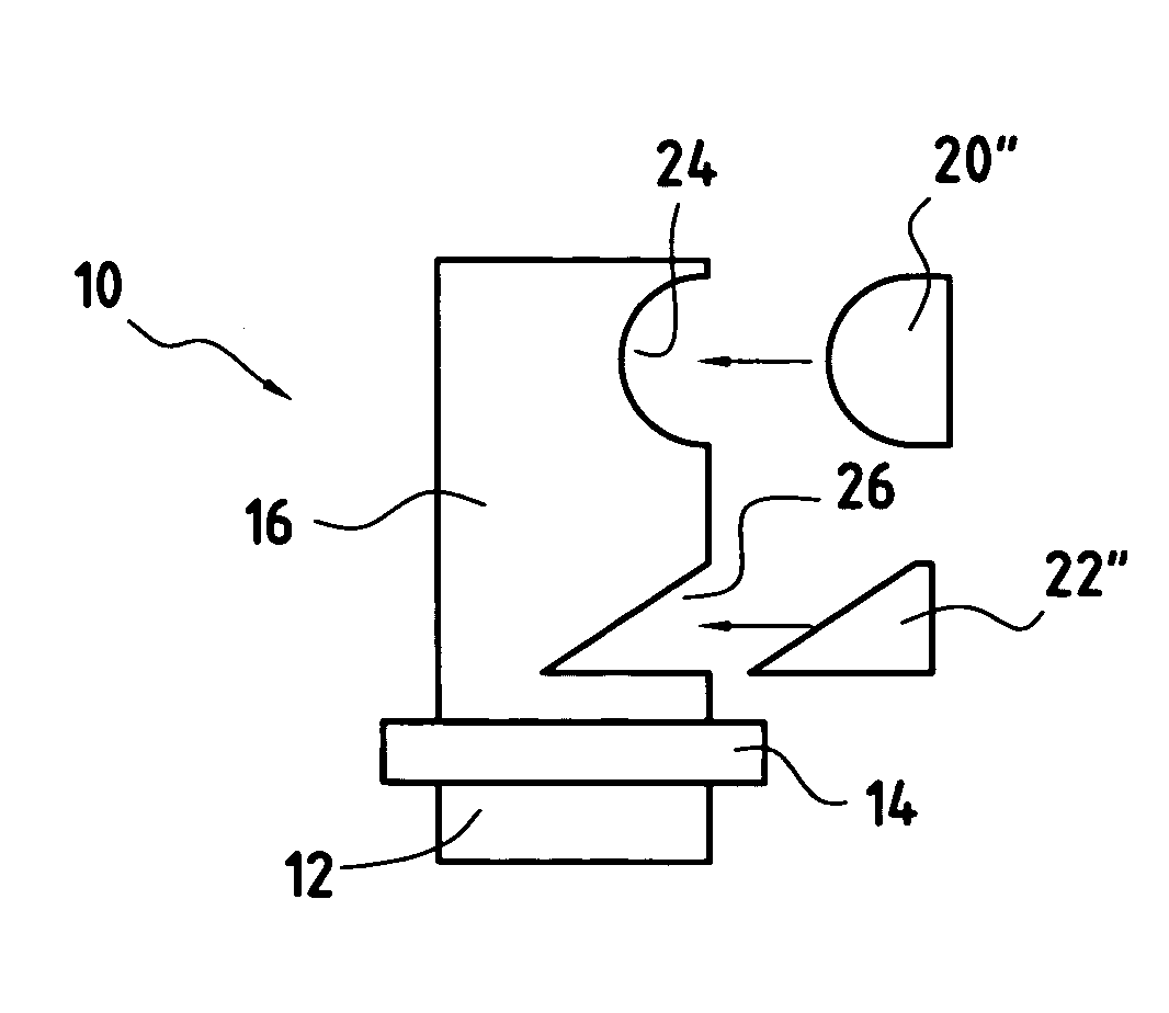
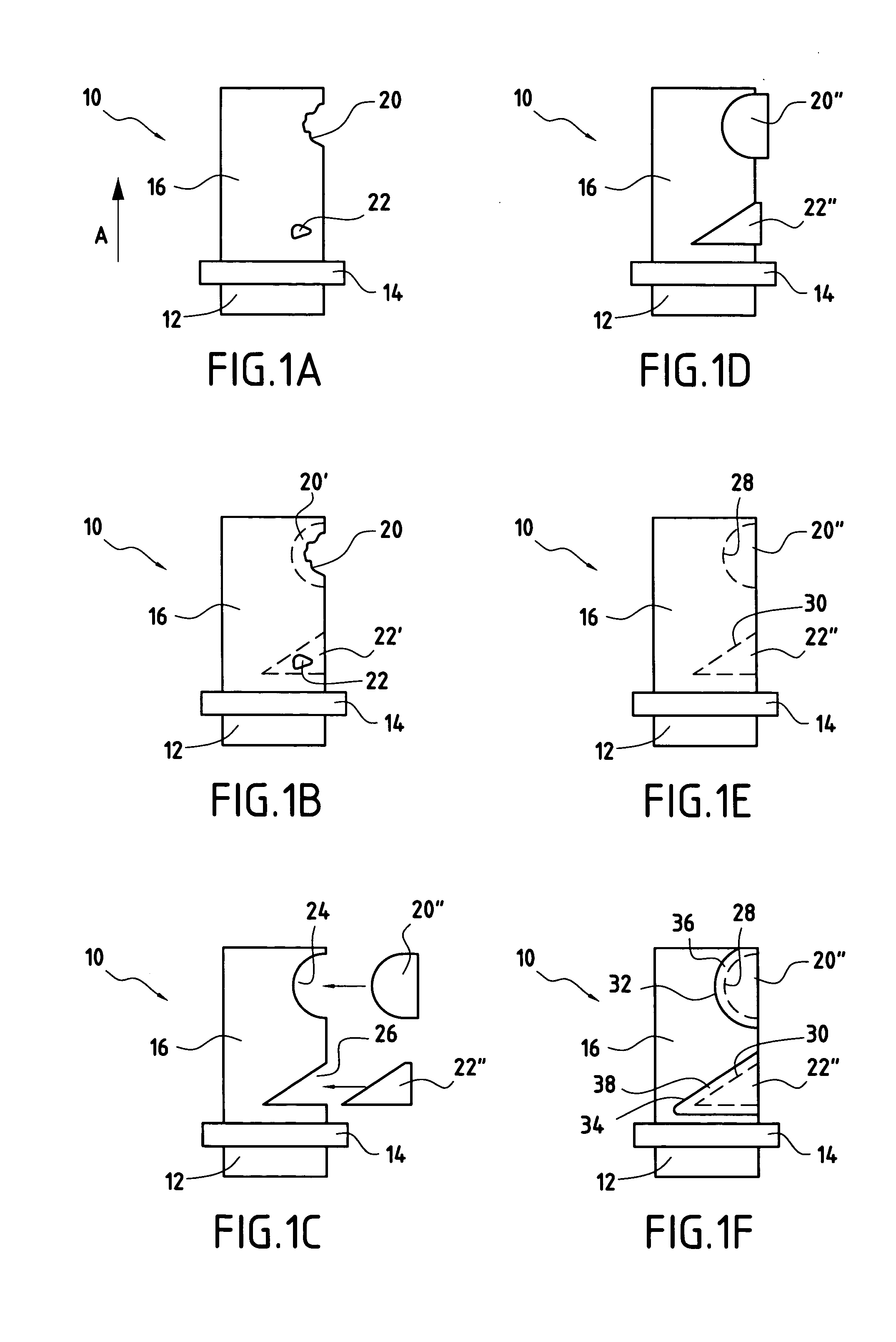
[0021] In a first preferred embodiment of the present invention, as illustrated in FIGS. 1A-1F, a localized damaged area of a blade member is repaired by cutting away a portion of the blade member generally conforming to the extent of the damaged area, and thereafter replacing the cut away portion with a similarly shaped replacement portion. This is generally advantageous because it minimizes the amount of the original constituent material removed from the blade member, thereby helping to largely maintain the original mechanical characteristics of the blade member.

[0022]FIGS. 1A-1F are side schematic views of a generalized blade member 10, particularly a blade member used in a turbomachine, such as a turbofan engine. In turbomachine applications, blade member 10 is made from any suitable metallic material, including metal alloys. Blade member 10, as illustrated, includes, for example, a root 12 for mounting blade member 10 in a disk (not shown) in a known manner, such as a dovetail...


PUM

PropertyMeasurementUnit
pressureaaaaaaaaaa
sizeaaaaaaaaaa
widthaaaaaaaaaa

Abstract

A method of repairing blade members, especially blade members in a turbomachine is provided. In one example, a damaged portion of a blade member is cut away from the blade member, by milling for example. The extent of the cut away portion generally corresponds in size and / or shape to the damaged area. A replacement portion is then welded into place in the resultant void in the blade member. The resulting weld seam is then burnished or deep rolled in order to cold work the blade member material at the weld seam. This induces compressive residual stresses in the blade member that counteract tensile residual stresses in and around the weld seam caused by the welding, and therefore strengthens the resulting repaired structure. The disclosed process particularly useful for repairing bladed disks (bladed monoblock disks) where individual blades cannot be removed for replacement or repair.

Description

FIELD OF THE INVENTION [0001] The present invention relates to methods of repairing metallic blade members and, more generally, metallic blade-shaped members generally having a cross-sectional shape with an effective width that is substantially greater than a thickness thereof. The present invention especially, but not solely, relates to aerodynamic blade members used in turbomachinery such as turbines, aircraft engines, and the like. DESCRIPTION OF RELATED ART [0002] Many known devices use bladed members, including turbines, jet aircraft engines, and the like. Moreover, depending on the application, such bladed members are made from metal or special metal alloys, and can be generally expensive to manufacture, maintain, and repair. Yet, over time and in the course of normal operation, these blades are generally subject to damage due to aging and wear. They also occasionally experience damage due to external factors such as foreign object damage in jet engines, problems occurring dur...

Claims


Application Information

Patent Timeline
Patent Type & Authority Applications(United States)
IPC IPC(8): B23P6/00B23P19/04B23P9/02B24B39/00C21D7/08F01D5/00
CPCB23P6/005B23P9/02C21D7/08F01D5/005Y10T29/4973F05D2230/80Y10T29/49732Y10T29/49734Y10T29/49318Y02T50/673Y02T50/60
Inventor NTSAMA-ETOUNDI, MARIE-CHRISTINEPINTO, ERICRICHIN, CATHERINE
Owner SN DETUDE & DE CONSTR DE MOTEURS DAVIATION S N E C M A
Why Eureka
Try Eureka