Working fluid for heat pipe and method for manufacturing the same

a technology of working fluid and heat pipe, which is applied in the direction of heat exchange elements, chemistry apparatuses and processes, etc., can solve the problem of lowering the thermal conductivity of the heat pip

Inactive Publication Date: 2006-12-14
HON HAI PRECISION IND CO LTD
View PDF8 Cites 11 Cited by
  • Summary
  • Abstract
  • Description
  • Claims
  • Application Information

AI Technical Summary

Benefits of technology

[0006] A working fluid for a heat pipe includes a liquid solvent, a plurality of nano-particles dispersed in the liquid solvent, and a polymer stability agent configured for preventing the nano-particles from aggregating in the liquid solvent.

Problems solved by technology

However, the surface-active agent may cause a lot of foams, which may prevent the working fluid from flowing between the evaporating section of and the condensing section.
This result will greatly lower the thermal conductivity of the heat pipe.

Method used


Image

  • Working fluid for heat pipe and method for manufacturing the same
  • Working fluid for heat pipe and method for manufacturing the same
  • Working fluid for heat pipe and method for manufacturing the same

Examples


first embodiment

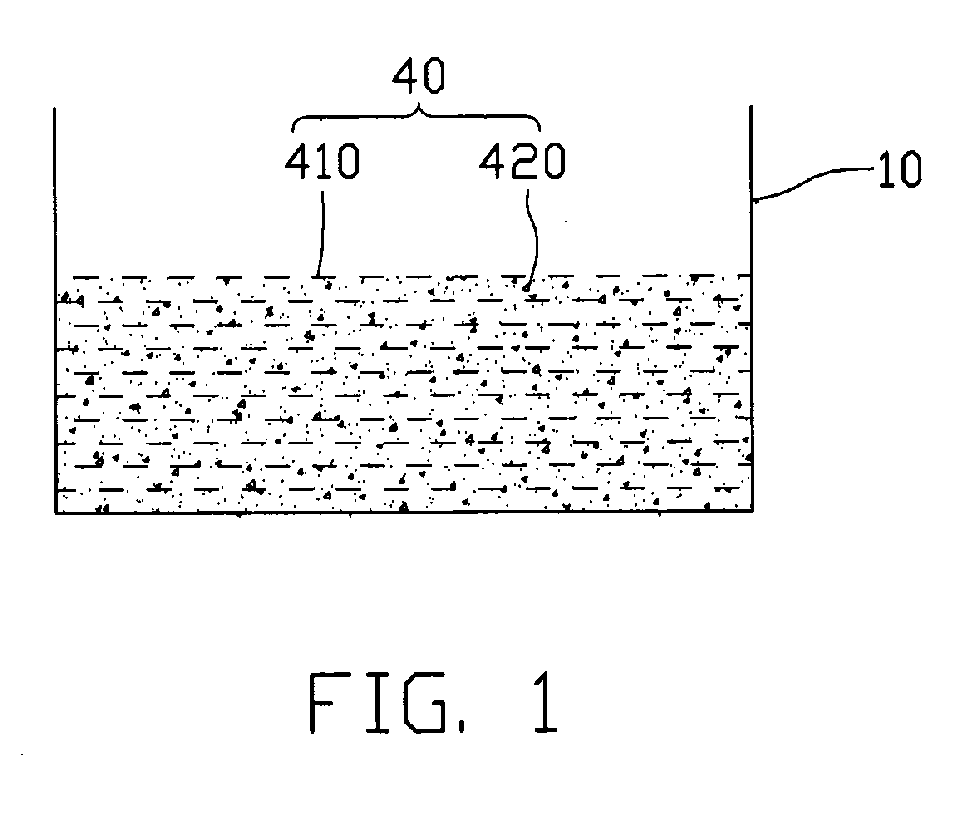
[0013] Referring to FIG. 1, there is shown a vessel 10 containing a working fluid 40 in accordance with a The working fluid 40 includes a liquid solvent containing a plurality of nano-particles 420 dispersed therein, and a polymer stability agent 410 is configured for preventing the nano-particles 420 from aggregating in the liquid solvent. The liquid solvent itself can be made of a substance suitable as a working fluid for a heat pipe, while, it can dissolve the polymer stability agent 410. The polymer stability agent 410 has a spatial chain configuration in structure, which can obstruct the nano-particles 420 from aggregating. In molecular structure, the polymer stability agent 410 can be a polar molecule or a non-polar molecule, so the corresponding liquid solvent can also be a polar solvent or a non-polar solvent. As a polar molecule, the polymer stability agent 410 can be poly vinyl alcohol (PVA) or poly vinyl pyrrolidone (PVP), then the corresponding liquid solvent can be a p...

second embodiment

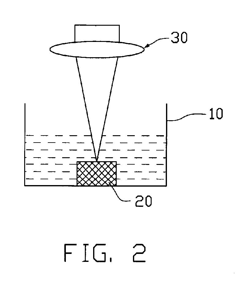
[0018]FIG. 2 shows an apparatus for manufacturing a working fluid 40 in accordance with a The apparatus includes a vessel 10 for holding a poly vinyl alcohol aqueous solution, a copper target 20 and a laser device 30. The copper target 20 is immersed in the poly vinyl alcohol aqueous solution, preferably, wholly immersed in the poly vinyl alcohol aqueous solution. The laser device 30 is used to bombard the copper target 20 to produce nano-scaled copper particles, so it can be located an appropriate distance away from the copper target 20. With such apparatus, the desired working fluid 40 can be manufactured via the following steps. Firstly, adjusting the laser device 30 to aim at the copper target 20, then bombarding the copper target 20 with a laser beam generated by the laser device 30 to produce nano-scaled copper particles. The produced particles then disperse into the poly vinyl alcohol aqueous solution, thus obtaining the desired working fluid 40 which include the poly vinyl ...

third embodiment

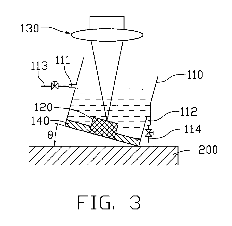
[0020]FIG. 3 shows an apparatus 100 for continuously manufacturing the working fluid 40 in accordance with a The apparatus 100 includes a vessel 110 containing the poly vinyl alcohol aqueous solution, a copper target 120, a laser device 130 and an ultrasonic device 140. The vessel 110 is arranged on a base 200, and the vessel 110 and the base 200 form an appropriate angle. The angle is in a range from above about zero degrees to about 60 degrees. The vessel 110 defines an inlet 111 and an outlet 112. The inlet 111 is connected with an input tube 113 with a valve configured thereon. The outlet 112 is connected with an output tube 114 with a valve configured thereon. The copper target 120 is arranged inside the vessel 110 and embedded with the poly vinyl alcohol aqueous solution. The laser device 130 is located an appropriate distance away from the copper target 120.

[0021] With the apparatus 100, the working fluid 40 can be continuously manufactured by the following steps. Firstly, a...


PUM

PropertyMeasurementUnit
angleaaaaaaaaaa
angleaaaaaaaaaa
stabilityaaaaaaaaaa

Abstract

A working fluid for a heat pipe includes a liquid solvent; a plurality of nano-particles dispersed in the liquid solvent; and a polymer stability agent configured for preventing the nano-particles from aggregating in the liquid solvent. A method for manufacturing the working fluid includes the steps of: providing a vessel containing a liquid solvent containing a polymer stability agent dispersed therein, the polymer stability agent being configured for preventing the created nano-particles from aggregating in the liquid solvent; arranging a target in the liquid solvent; and bombarding the target to create nano-particles, whereupon the nano-particles are dispersed into the polar solvent, thereby obtaining the working fluid.

Description

FIELD OF THE INVENTION [0001] The present invention generally relates to thermal dissipating materials, and more particularly to a working fluid for a heat pipe. The present invention also provides a method for manufacturing the working fluid. DESCRIPTION OF RELATED ART [0002] Electronic components such as semiconductor chips are becoming progressively smaller, while heat dissipation requirements are correspondingly increasing. In many contemporary applications, a heat pipe is one of most efficient systems for transmitting heat away from such components. [0003] A typical heat pipe is a vessel that includes a pipe, a wick and an amount of liquid working fluid. The wick is a capillary structure, and is fixed on an inner wall of the pipe. The liquid working fluid is sealed in the pipe and soaks the wick. One end of the heat pipe is an evaporating section, and another end of the heat pipe is condensing section. The evaporating section is disposed in thermal communication with an externa...

Claims


Application Information

Patent Timeline
Patent Type & Authority Applications(United States)
IPC IPC(8): C09K5/04
CPCC09K5/10
Inventor TUNG, TSAI-SHIH
Owner HON HAI PRECISION IND CO LTD
Why Eureka
Try Eureka